Strategy for fueling a diesel engine by selective use of fueling maps to provide HCCI+RVT, HCCI+IVC, HCCI+IVC+EVC, and CDcombustion modes

a technology of fueling map and diesel engine, which is applied in the direction of electric control, brake system, instruments, etc., can solve the problems of difficult control of combustion rate, achieve the effect of enhancing the use of hcci combustion, reducing the generation of undesired constituents, and improving thermal efficiency

Inactive Publication Date: 2005-12-29
INT ENGINE INTPROP CO LLC
View PDF14 Cites 28 Cited by
  • Summary
  • Abstract
  • Description
  • Claims
  • Application Information

AI Technical Summary

Benefits of technology

[0012] The present invention relates to an engine and method of operation for enhancing the use of HCCI combustion in a diesel engine toward objectives that include reducing the generation of undesired constituents in engine exhaust, especially soot and NOx, and improving thermal efficiency. The invention is embodied in the fuel injection control strategy, a strategy that is programmed in an associated processing system.
[0016] The invention disclosed in the present application provides what may be considered an enhancement to the HCCI+VVT mode described in application Ser. No. 10 / 874,668. One way of considering the enhancement is by defining the HCCI+VVT mode to comprise two modes rather than a single mode. Such a definition should not necessarily be construed to mean that the limits, or boundaries, of HCCI+VVT mode remain unchanged. To the contrary, by providing two distinct modes for what had heretofore been disclosed as only a single mode, it is believed possible to further extend the useful range of HCCI combustion, especially in the direction of higher speeds and loads.
[0018] What is new in the present application is the HCCI+IVC+EVC mode. Over a range of engine speeds and loads greater than those during which the engine operates in the HCCI+IVC mode, but less than those during which the engine operates in the CD+RVT mode, the variable valve timing system operates to delay the closing of the exhaust valves in comparison to the timing of their closing during the HCCI+IVC mode. By retarding exhaust valve closing, the percentage of residual hot gases in the cylinders can be reduced, thereby providing decreased cylinder temperature and pressure, a result beneficial to reducing certain engine emissions like NOx.
[0026] The control system controls the fueling system to extend the load / speed range over which HCCI combustion occurs by a) fueling one or more combustion chambers over a relatively lower speed / load range to create a substantially homogeneous air-fuel charge within each such combustion chamber during a corresponding engine cycle and compressing each charge to auto-ignition without introducing any additional fuel after auto-ignition during that corresponding engine cycle, and b) decreasing the effective compression ratio of each such combustion chamber and fueling each such combustion chamber with increased fueling over a relatively higher speed / load range to create a substantially homogeneous air-fuel charge within each such combustion chamber during a corresponding engine cycle, compressing each charge to auto-ignition without introducing any additional fuel after auto-ignition during that corresponding engine cycle, and retarding the timing of exhaust valve closing relative to the timing of exhaust valve closing in the relatively lower speed / load range.

Problems solved by technology

At higher engine speeds and larger engine loads, the rate of combustion is difficult to control.
Consequently, known engine control strategies may utilize HCCI only at relatively lower speeds and smaller engine loads.

Method used


Image

  • Strategy for fueling a diesel engine by selective use of fueling maps to provide HCCI+RVT, HCCI+IVC, HCCI+IVC+EVC, and CDcombustion modes
  • Strategy for fueling a diesel engine by selective use of fueling maps to provide HCCI+RVT, HCCI+IVC, HCCI+IVC+EVC, and CDcombustion modes
  • Strategy for fueling a diesel engine by selective use of fueling maps to provide HCCI+RVT, HCCI+IVC, HCCI+IVC+EVC, and CDcombustion modes

Examples


Embodiment Construction

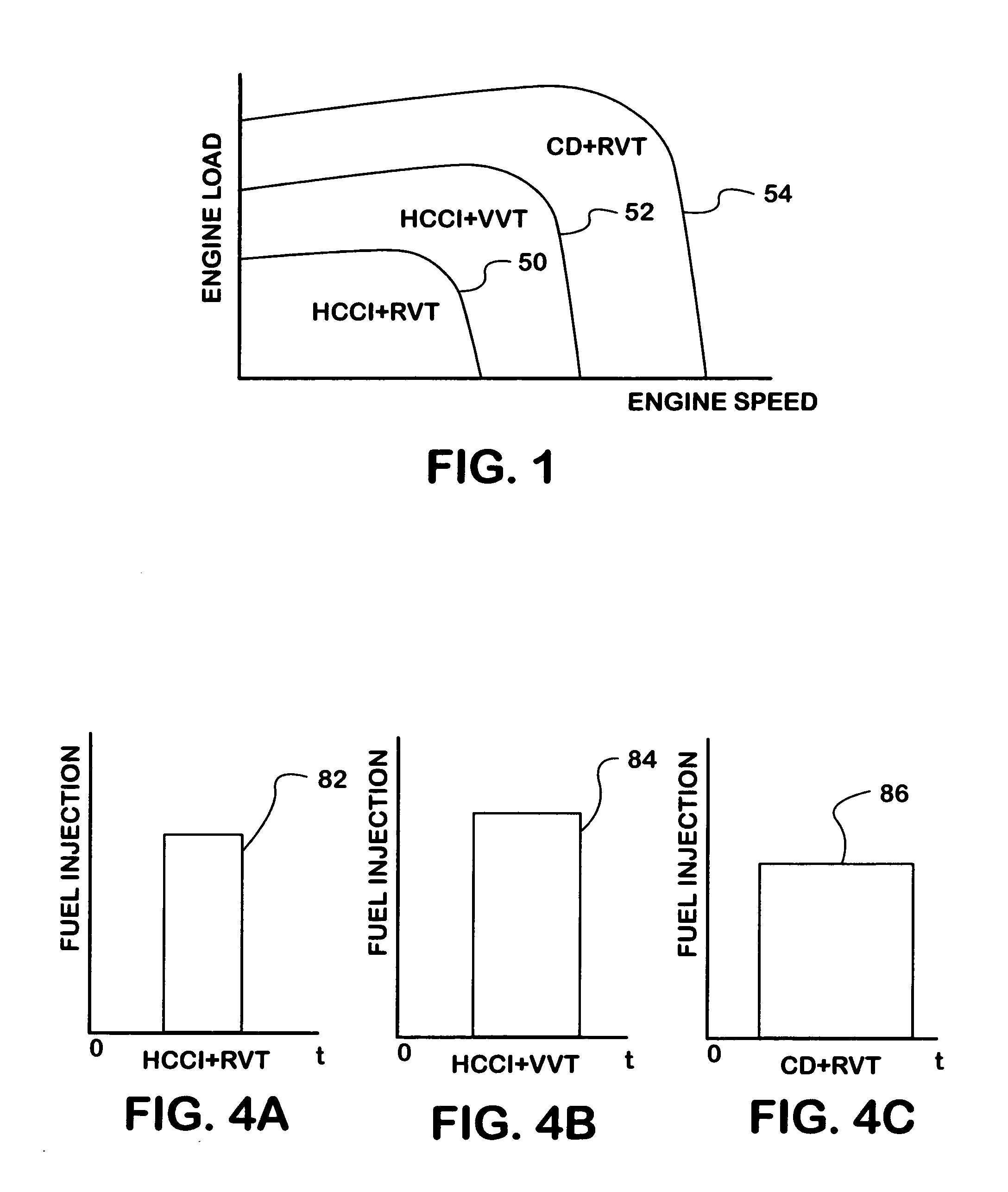
[0038]FIG. 1 is a graph whose vertical axis represents engine load and whose horizontal axis represents engine speed. At the origin of the graph, engine load is zero, and engine speed is zero. Respective solid lines 50, 52, and 54 demarcate three zones labeled HCCI+RVT, HCCI+VVT, and CD+RVT. RVT stands for regular valve timing of the engine intake valves, and VVT, variable valve timing of the engine intake valves.

[0039] Zone HCCI+RVT covers an area that encompasses various combinations of relatively smaller engine loads and relatively lower engine speeds. Zone HCCI+VVT covers an area that encompasses various combinations of relatively larger engine loads and relatively higher engine speeds than those of zone HCCI+RVT. Zone CD+RVT covers an area that encompasses various combinations of still relatively larger engine loads and still relatively higher engine speeds than those of zone HCCI+VVT. When a compression ignition engine is operating at a speed and load that falls within Zone H...


PUM


Abstract

A compression ignition engine (60) has a control system (66) for processing data, one or more combustion chambers (62), and fuel injectors (64) for injecting fuel into the chambers. The control system controls fueling by processing engine speed and load, to select one of four fueling modes (HCCI+RVT, HCCI+IVC, HCCI+IVC+EVC, and CD+RVT) for operating the engine (FIG. 5). When HCCI+RVT mode is selected, intake valves operate with regular valve timing (RVT), and the engine is fueled to cause homogeneous-charge compression-ignition (HCCI) combustion. When HCCI+IVC mode or HCCI+IVC+EVC mode is selected, intake valve timing is changed relative to RVT, and the engine is fueled to cause HCCI combustion. When the processing selects the CD+RVT mode, the intake valves operate with RVT, and the engine is fueled to cause CD combustion. In HCCI+IVC+EVC mode, exhaust valve closing is retarded relative to its timing in HCCI+IVC mode to reduce cylinder pressure and temperature.

Description

REFERENCE TO A RELATED APPLICATION AND PRIORITY CLAIM [0001] This application is a continuation-in-part, and claims priority, of pending application Ser. No. 10 / 874,668, filed 23 Jun. 2004.FIELD OF THE INVENTION [0002] This invention relates generally to internal combustion engines. More specifically it relates to a control strategy for selectively utilizing homogeneous-charge compression-ignition (HCCI) in a way that takes advantage of HCCI's attributes in different ways during different modes of operation of an engine that has variable valve timing. More specifically the invention claimed herein will be seen to relate to a strategy for fueling the engine to cause HCCI combustion during a first mode (HCCI+RVT), to cause HCCI combustion during a second mode (HCCI+IVC) where variable valve timing causes intake valves to close at different delayed times during the engine cycle than during the first mode, to continue HCCI combustion during a third mode (HCCI+IVC+EVC) where variable val...

Claims


Application Information

Patent Timeline
Patent Type & Authority Applications(United States)
IPC IPC(8): B60T7/12F02B1/12F02B3/06F02B5/00F02B17/00F02D13/02F02D15/04F02D41/30G06G7/70
CPCF02B1/12F02B3/06F02D13/0234F02D13/0269Y02T10/18F02D41/3035F02D2041/001Y02T10/128Y02T10/142F02D15/04Y02T10/12
Inventor LIU, ZHENGBAIWEI, PUNINGSULLIVAN, DENNIS KELLY
Owner INT ENGINE INTPROP CO LLC
Why Eureka
Try Eureka