[0015] As a consequence of the inclination of the longitudinal central axis of the antivibration element relative to the longitudinal
central plane of the implement, the antivibration element can have a greater length without changing the dimensions of the implement. As a result, the dampening properties of the antivibration element can be better adapted; in particular, the dampening can be made softer. The design of the antivibration element is less a function of the overall size of the implement since the antivibration element can be fit better into the installation space that is available due to the inclination relative to the longitudinal central plane.
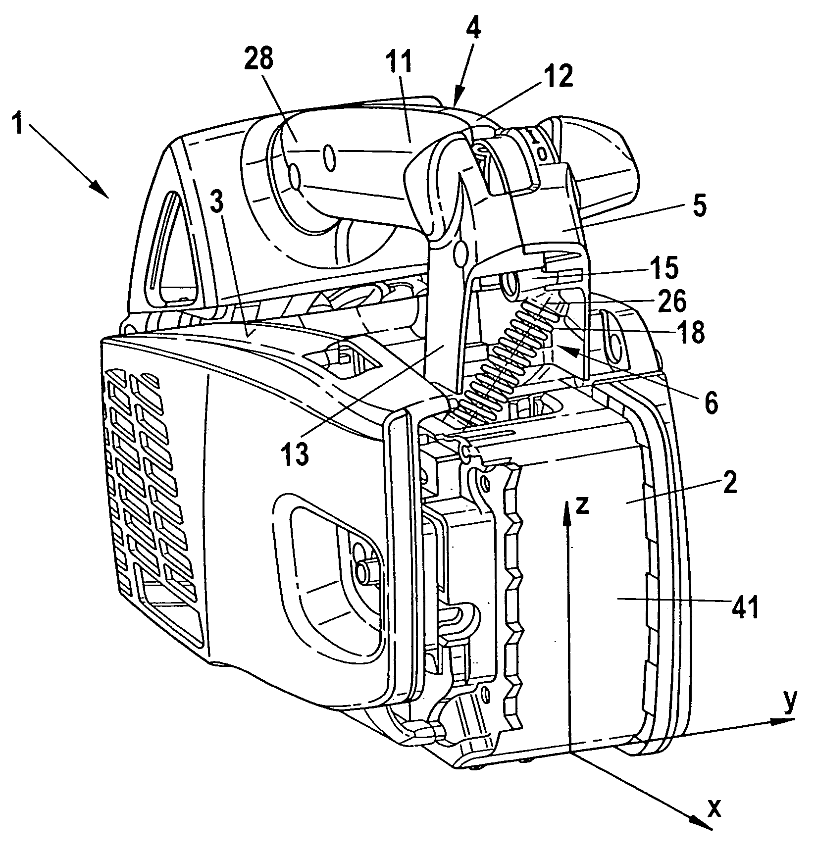
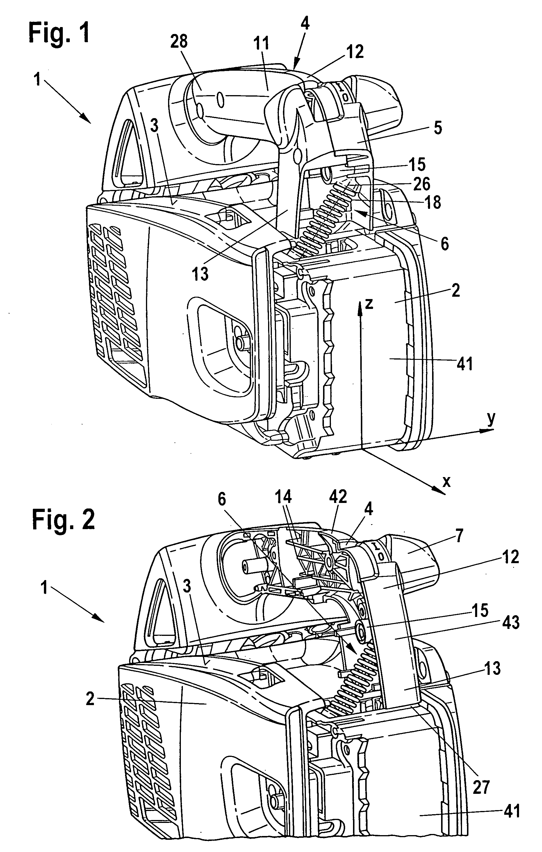
[0016] Pursuant to one embodiment, the first antivibration element connects a first end of the upper handle that faces the tool to the housing. In particular in the front region of the implement that faces the tool, the installation space that is available is limited by the
internal combustion engine, so that only a small installation space is available for the antivibration element. Due to the inclination of the antivibration element relative to the longitudinal central plane, the antivibration element can be secured to the housing of the implement laterally adjacent to the internal
combustion engine, so that the installation space that is available can be well utilized. The first antivibration element is advantageously connected to the handle via a first connection element, and to the housing via a second connection element. A simple
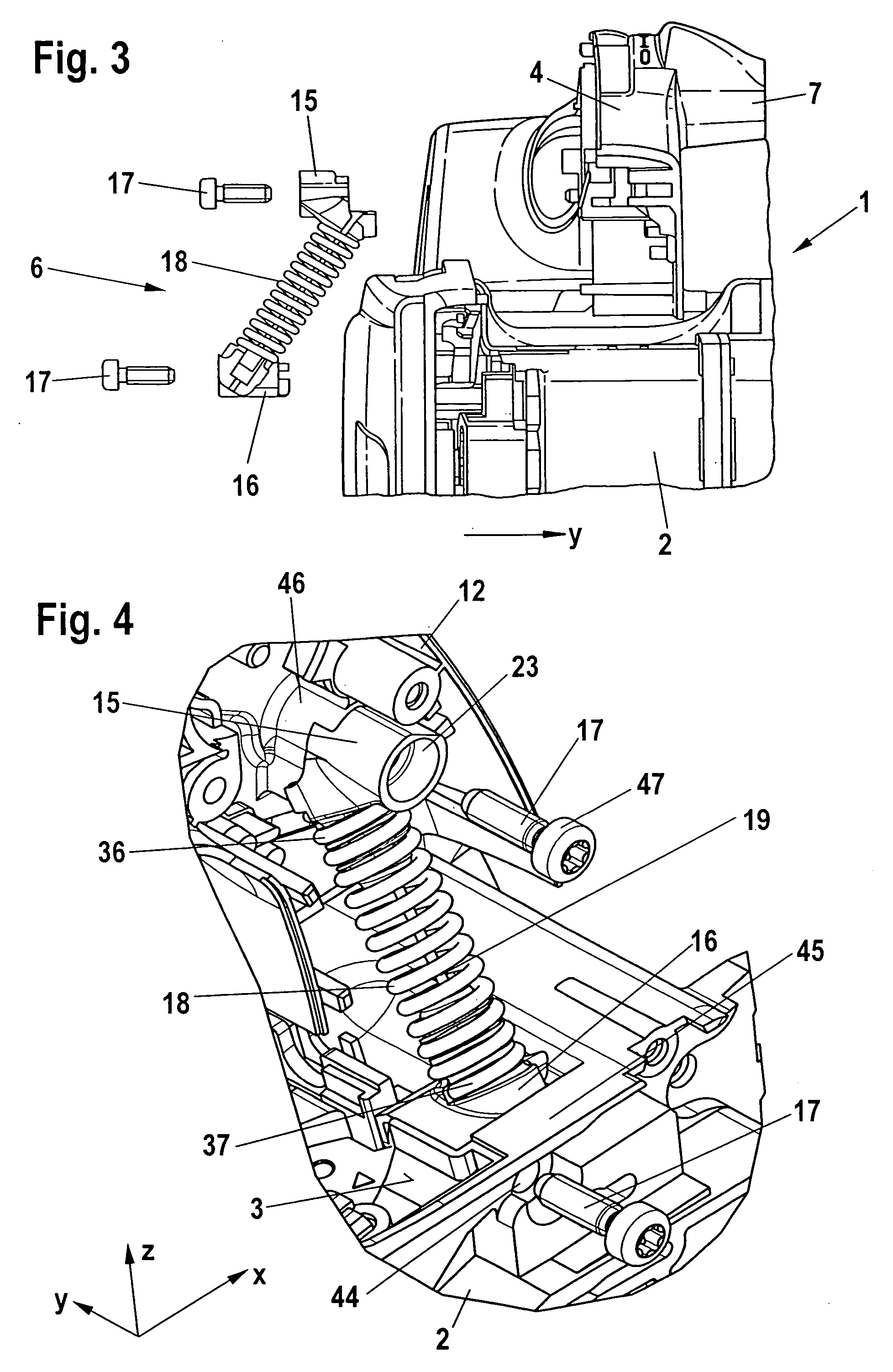
assembly of the implement can be achieved by respectively securing the connection elements to the housing and the handle respectively via at least one securement or fastening element, in particular a screw. To simplify the
assembly, pursuant to one embodiment both connection elements are assembled in one direction. As a result, the antivibration element can be completely assembled in one position of the implement, thus reducing
assembly time. At least one connection element advantageously has a bore for a fastening element, whereby the longitudinal central axis of the bore is inclined relative to the longitudinal central axis of the antivibration element.
[0017] To achieve a good dampening effect, pursuant to one embodiment the first antivibration element includes a
coil spring. Since antivibration elements having coil springs require a large installation space, the inclination relative to the longitudinal central plane of the implement is particularly advantageous with such antivibration elements. The
coil spring is expediently held at at least one end on a guide means. The guide means is in particular in the form of a thread. As a result, the
coil spring can easily be screwed into the guide means. It is easy to exchange the guide means and / or the spring to adapt the dampening. In order to adapt the dampening effect to the respective load condition, pursuant to one embodiment the guide means at one end section of the coil spring rests against the coil spring, and at a guide section adjoining the end section the coil spring is guided along the guide means with play. In the non-loaded state, the coil spring is held only at the end sections. When a loading of the coil spring perpendicular to its longitudinal axis occurs, the guide section of the coil spring also rests at least partially against the guide means. The effect of spring length is thereby reduced, so that the dampening effect of the coil spring increases. As a result, a good vibrational dampening and a good guide characteristic of the implement are achieved. The spacing of the guide means relative to the coil spring in the guide section, as measured in the radial direction relative to the longitudinal central axis of the antivibration element, advantageously decreases toward the center of the coil spring. As a result, the dampening effect increases as the deformation increases, resulting in a progressive spring characteristic that translates into a favorable guide characteristic.
[0018] The guide means is advantageously formed on a threaded plug that extends into the interior of the coil spring. In this connection, the threaded plug is in particular monolithically formed with a connection element. To enable a reliable guidance of the implement even if the coil spring breaks, pursuant to one embodiment the antivibration element is provided with a means for protecting against separation. Such protection means expediently include a connecting element, each end of which is held on a connection element, and which in the direction of the longitudinal central axis of the antivibration element is held with play in the non-loaded state of the antivibration element. In such a non-loaded state, or with slight deformations of the coil spring, the spring effect is not adversely affected by the means for protecting against separation. Should the deformation become greater than the play of the means for protecting against separation, such protection means represents a limitation of the deformation of the coil spring. In the event that the coil spring breaks, the two connection elements are interconnected via the connecting element of the means for protecting against separation, so that the handle does not separate from the housing. In this connection, the inclination of the antivibration element is expediently such that the means for protecting against separation holds the handle on the housing at a favorable angle.
[0020] A simple construction of the implement is achieved if the first end of the upper handle and the tubular handle that faces the tool is secured to the housing via the first antivibration element. As a result, both handles can be connected by a common antivibration element, so that a second antivibration element can be eliminated.

