Intake control device for internal combustion engine

a control device and internal combustion engine technology, applied in the direction of machines/engines, other domestic objects, mechanical apparatus, etc., can solve the problems of idling rotating speed increase, fuel consumption increase, seizure of the throttle body, etc., to shorten the working time needed for adjusting engine output and the full-closing position

Active Publication Date: 2006-01-05
DENSO CORP
View PDF4 Cites 39 Cited by
  • Summary
  • Abstract
  • Description
  • Claims
  • Application Information

AI Technical Summary

Benefits of technology

[0011] In view of the foregoing problems, it is an object of the present invention to provide an intake control device for an internal combustion engine, the intake control device having a structure, in which a throttle valve, a shaft, and a rotary driver can be assembled together under a predetermined assembling condition such as a mounting angle. It is anothe

Problems solved by technology

As a result, idling rotating speed may increase, and fuel consumption may increase.
As a result, the throttle valve may cause seizure with the throttle body 101.
In this case, the throttle valve may not normally perform opening and closing motions, and the amount of intake air cannot be properly controlled in the vicinity of idling opening degree.
Howeve

Method used


Image

  • Intake control device for internal combustion engine
  • Intake control device for internal combustion engine
  • Intake control device for internal combustion engine

Examples


first embodiment

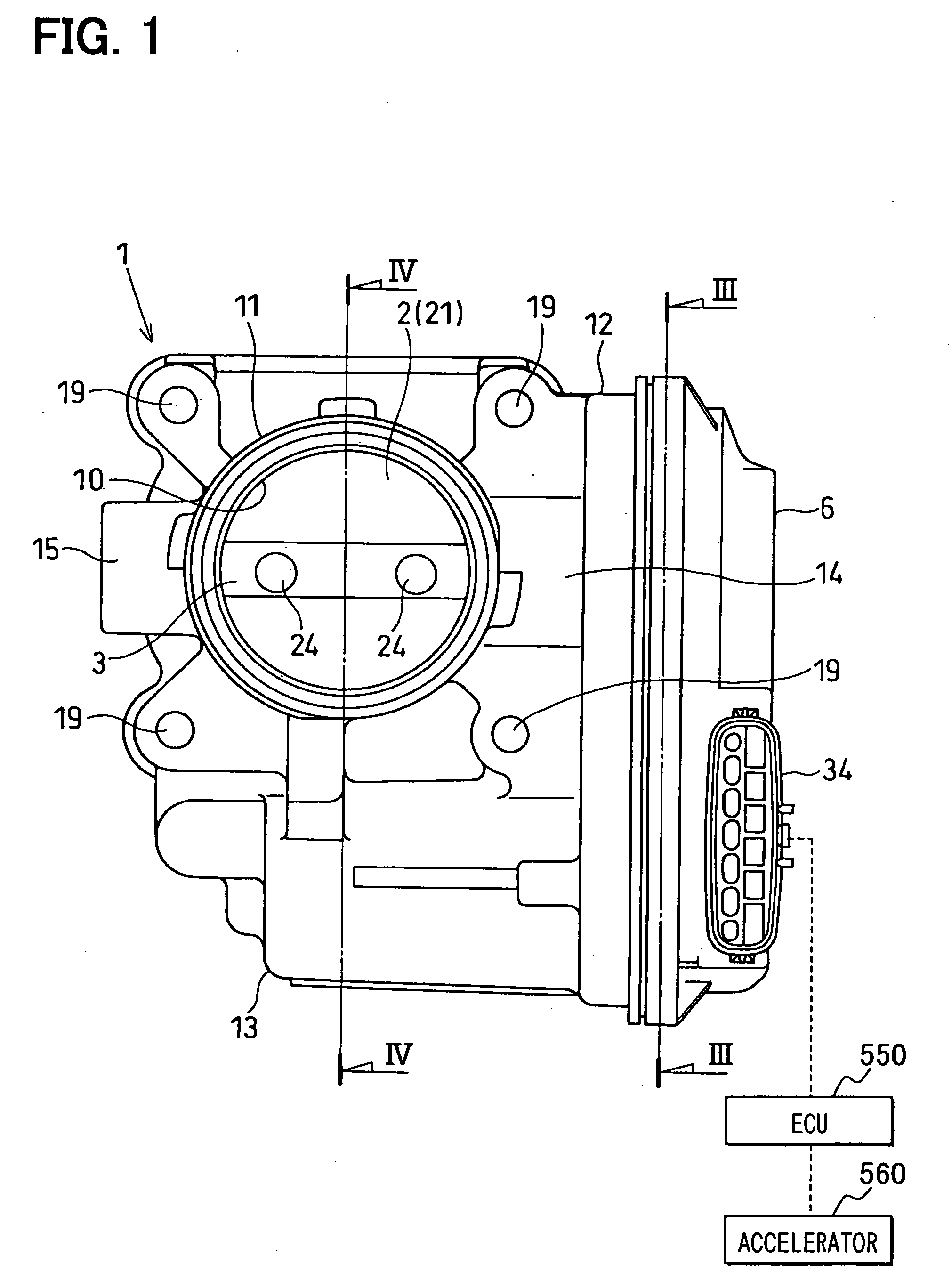
[0032] A throttle control device (intake air control device) changes an amount of intake air flowing into respective cylinders (combustion chambers) of the internal combustion engine such as a multi-cylinder gasoline engine, in accordance with an accelerator position (an accelerator manipulated variable) to control engine rotation speed or engine torque. The throttle control device is an electronic control type throttle control device, in this embodiment.

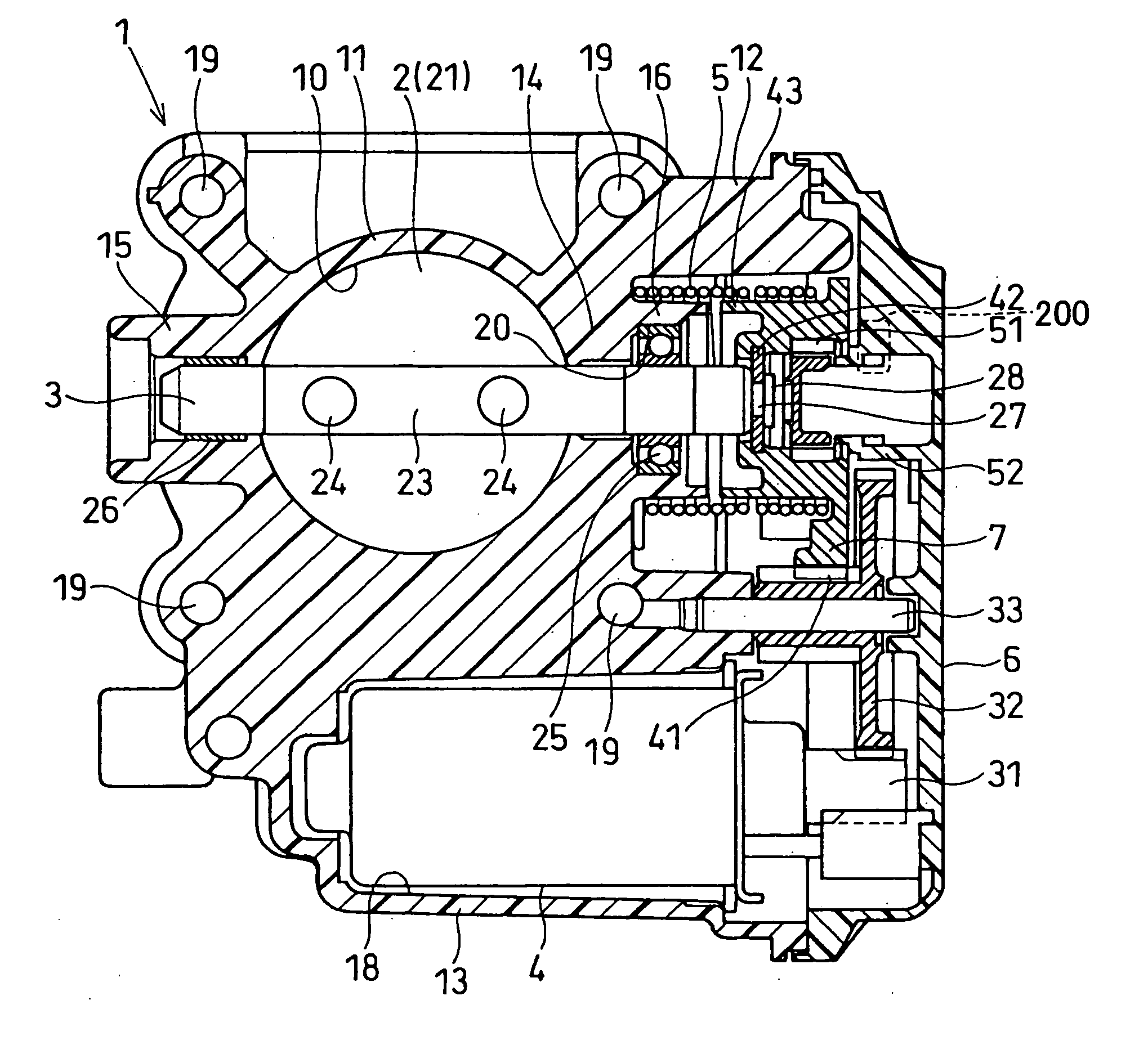
[0033] As shown in FIGS. 1 to 7, the throttle control device includes a throttle body 1, a throttle valve 2, a throttle shaft 3, a motor 4, a coil spring 5, and an ECU (engine control unit) 550. The throttle body 1 has an intake passage that is communicated to respective cylinders of an engine 500. The throttle valve 2 controls an amount of intake air flowing through the intake passage. The throttle shaft 3 rotates together with the throttle valve 2. The motor 4 drives the throttle valve 2 in an opening direction and / or a closing d...

second embodiment

[0064] As shown in FIG. 8A, a columnar-shaped coupling 27 is provided to the one axial end of the throttle shaft 3, and multiple fitting recesses 61 are formed to be dented radially outward from the hole wall surface of the circular-shaped fitted hole 44 formed in the metallic member 42 on the inner periphery of a valve gear 7. The fitting recesses 61 are substantially triangular-shaped through-holes or grooves.

[0065] In this structure, the coupling 27 is clearance-fitted into the fitted hole 44, so that the outer periphery of the coupling 27 and the inner periphery of the fitted hole 44 come into line contact with each other. Therefore, relative rotating movement between the throttle shaft 3 and the valve gear 7 are not restricted in the fit state prior to crimping and fixing the throttle shaft 3 and the valve gear 7. Besides, the full-closing clearance can be finely adjusted by rotating the throttle shaft 3 while abutting the full-closing stopper part 47 of the valve gear 7 again...

third embodiment

[0073] As shown in FIGS. 9, 10A to 10C, the bore wall portion 11 of the throttle body 1 is provided with the first and the second valve bearing portions 14, 15 that rotatably support both ends of the throttle shaft 3. The cylindrical bearing member (bearing) 26 is press fitted onto the inner periphery of the shaft insertion hole of at least one of the first and the second valve bearing portions 14, 15. The bearing 26 is a dry bearing, a slide bearing, a thrust bearing, or a bearing bush. The bearing 26 has a slide hole 53, which rotatably supports one axial end of the throttle shaft 3 on the side opposite to the valve gear 7 such that the throttle shaft 3 is slidable in the rotating direction. The bearing 26 is integrally formed of a sintered bearing material of excellent abrasion resistance to be in a predetermined substantially cylindrical shape.

[0074] The coupling 27 is provided to the one axial end of the throttle shaft 3 to be crimped and fixed to the inner periphery of the va...


PUM

PropertyMeasurementUnit
Angleaaaaaaaaaa
Densityaaaaaaaaaa
Deformation enthalpyaaaaaaaaaa

Abstract

An intake control device for an engine includes a throttle body that defines a throttle bore, which is substantially circular-shaped in cross section, through which intake air flows. A throttle valve is rotatably assembled in the throttle bore of the throttle body. The throttle valve rotates integrally with a shaft. One axial end of the shaft is connected to a rotary driver, so that the rotation angle of the throttle valve is changed via the shaft. The rotary driver defines a fitted hole, to which the one axial end of the shaft is clearance fitted. The rotary driver defines a fitting recess dented radially outward from the hole wall surface of the fitted hole. The one axial end of the shaft includes a coupling that is crimped and fixed to the rotary driver in the state of being fitted to the fitted hole.

Description

CROSS REFERENCE TO RELATED APPLICATIONS [0001] This application is based on and incorporates herein by reference Japanese Patent Applications No. 2004-193807 filed on Jun. 30, 2004 and No. 2005-23469 filed on Jan. 31, 2005. FIELD OF THE INVENTION [0002] The present invention relates to an intake control device for an internal combustion engine, the intake control device controlling an amount of intake air drawn into a cylinder of an internal combustion engine. More particularly, the present invention relates to an intake control device, in which an actuator is driven in accordance with an accelerator position to control a rotation angle of a throttle valve rotatably accommodated in a throttle bore of a throttle body. BACKGROUND OF THE INVENTION [0003] A conventional throttle control device for an internal combustion engine is disclosed in U.S. Pat. No. 6,543,417B2 (JP-A-2002-371866). The throttle control device includes a throttle body, a throttle valve, and an engine control device...

Claims


Application Information

Patent Timeline
IPC IPC(8): F02D11/10F16K1/22
CPCF02D11/10Y10T29/49423F02D11/107
Inventor KADO, HIROYUKIMAKINO, ISAOTANIMURA, HIROSHISHIMADA, HIROKI
Owner DENSO CORP
Why Eureka
Try Eureka