Stripe removal system

Active Publication Date: 2006-01-05
WATERBLASTING
View PDF31 Cites 18 Cited by
  • Summary
  • Abstract
  • Description
  • Claims
  • Application Information

AI Technical Summary

Benefits of technology

[0011] It is an object of this invention to provide a vacuum recovery truck mounted stripe removal system having a compact unit for safe, fast over-the-road travel to job sites.
[0012] It is another object of this invention to provide a unit that is quickly deployed, with hoses not having to be disconnected, and in operation at the job site.
[0013] It is a further object of this invention to provide a tractor mounted blast head that is hydraulically articulated from left to right an

Problems solved by technology

The use of these carbide teeth and grinding wheels results in an undesirable trench or groove in the road.
For example, paint, when used for roadway marking, penetrates into the pavement, perhaps ⅛-⅜ inch, so that mere surface removal of the paint is not sufficient to remove the marking.
For example, a pavement marking removal technique that uses abrasive wheels or teeth can create excessive heat which may be suitable for removing painted markings but can melt thermoplastic materials causing equipment to gum up, by reconstituting the thermoplastic.
Because of the position of the driver and the cab body of the prime-mover, it

Method used


Image

  • Stripe removal system
  • Stripe removal system
  • Stripe removal system

Examples


Example

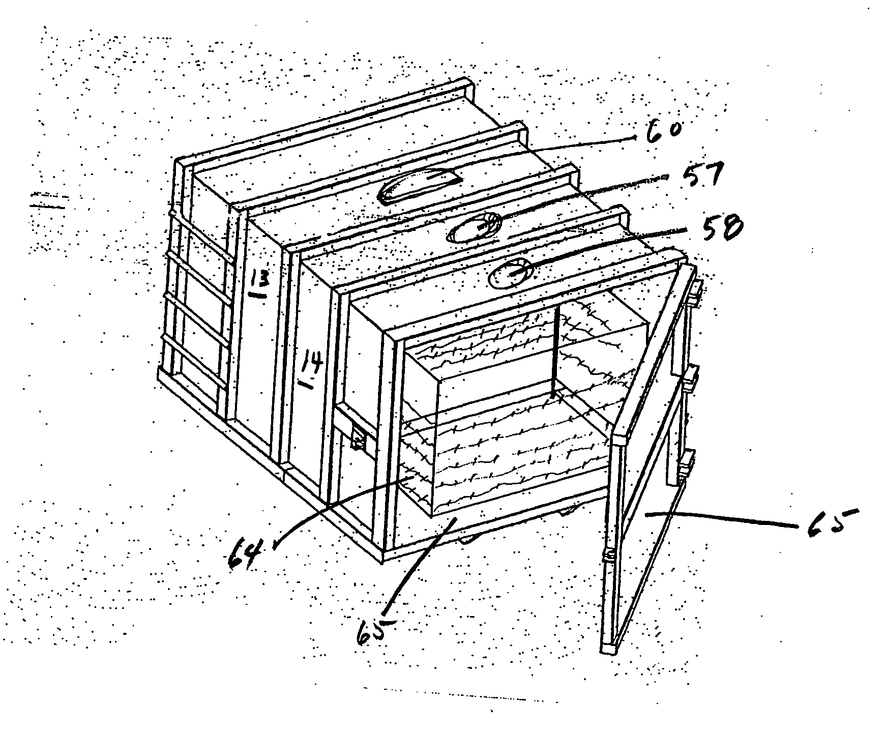
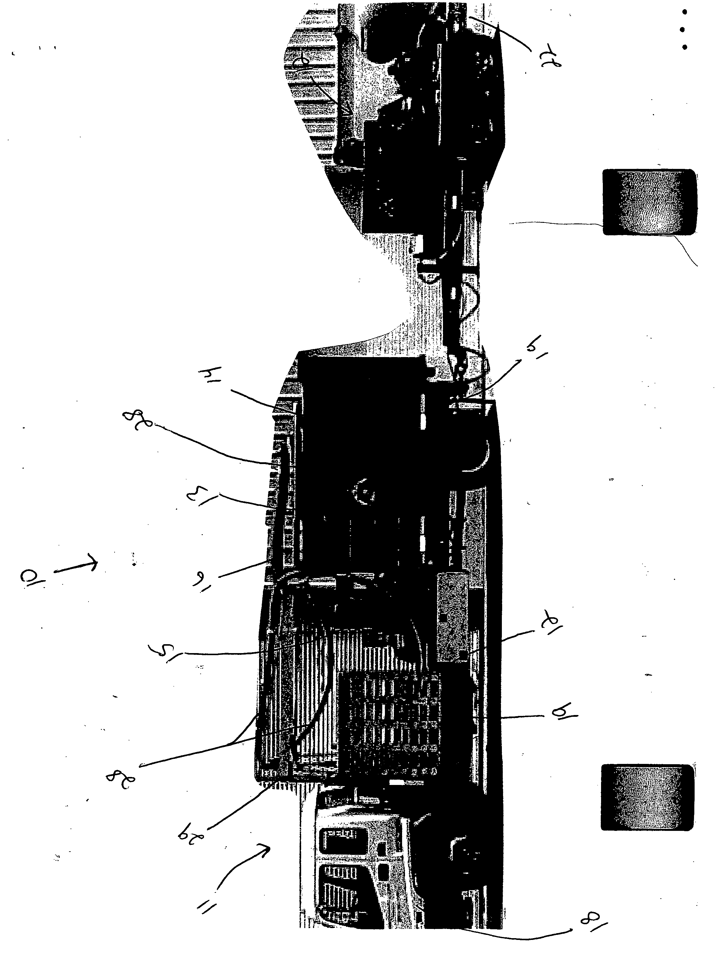
[0026] The paint removal system 10, shown in FIG. 1, includes a prime-mover truck 11 and a trailer 12. The truck has a forward cab-over 18 for the driving controls and operator. Mounted on the bed 12 of the truck is the water reservoir 13 and the sump 14 or vacuum chamber. The reservoir and sump are interconnected by a strategically positioned duct for continuous dumping of filtered wastewater when operating from a fixed position where liquid is supplied to the high pressure pump by a means other than the reservoir 13.

[0027] The sump 14 is positioned on the rear end of the bed 12. The rear portion 19 of the bed is pivotally mounted on the truck frame and hydraulicly powered to move in the vertical plane permitting dumping of the contents of the sump 14. The sump 14 is connected to the vacuum pump 15 by hose 16. The intake of a high power vacuum pump capable of approximately 1100 CFM (cubic feet per minute) is connected to the vacuum tank. The vacuum tank and pump are also mounted o...


PUM

PropertyMeasurementUnit
Pressureaaaaaaaaaa
Poweraaaaaaaaaa
Sizeaaaaaaaaaa

Abstract

A system for removing paint and other coatings from hard surfaces is mounted on a truck for over-the-road travel. The truck bed carries a high power vacuum pump, a self propelled tractor with an attached blast head, a liquid reservoir, a sump or vacuum tank, and a ramp for loading the tractor. The reservoir is connected to a low pressure pump that transfers water to the high pressure pump. The high pressure pump is connected to the blast head by a high pressure hose. A vacuum hose is connected to the sump which has an internal enclosure for separating the waste materials from the liquid for easy dumping of semi dried materials.

Description

FIELD OF THE INVENTION [0001] This invention relates to the field of high pressure water cleaning devices for highways, runways, parking decks, and other hard surfaces. PRIOR ART BACKGROUND [0002] The use of paint stripes on road surfaces is the accepted method to indicate vehicle lanes, crossing lanes, parking areas and numerous other indicators. Various pavement marking techniques are known, including the use of traffic paint, thermoplastic, epoxy paint and preformed tapes. Common pavement surfaces are asphalt and concrete. Most pavement marking systems are intended to be as durable and permanent as possible, and resistant to weathering and wear from traffic. The removal of such striping is typically required when the road is to be resurfaced or if the indication is to be changed. The removal of such stripes is typically performed by use of abrasive wheels, grinding teeth, or the blasting of abrasive particles against the material to be removed. The use of these carbide teeth and ...

Claims


Application Information

Patent Timeline
IPC IPC(8): B08B5/04
CPCE01H1/103B08B3/02
Inventor CROCKER, JAMES P.
Owner WATERBLASTING
Why Eureka
Try Eureka