Pixel cell with a controlled output signal knee characteristic response

a pixel cell and output signal technology, applied in the field of pixel cell transistors, can solve the problems of limiting the dynamic range of the pixel, pixel cells are easily saturated, and the electric dynamic range is limited on the upper end

Active Publication Date: 2006-01-05
APTINA IMAGING CORP
View PDF7 Cites 22 Cited by
  • Summary
  • Abstract
  • Description
  • Claims
  • Application Information

AI Technical Summary

Benefits of technology

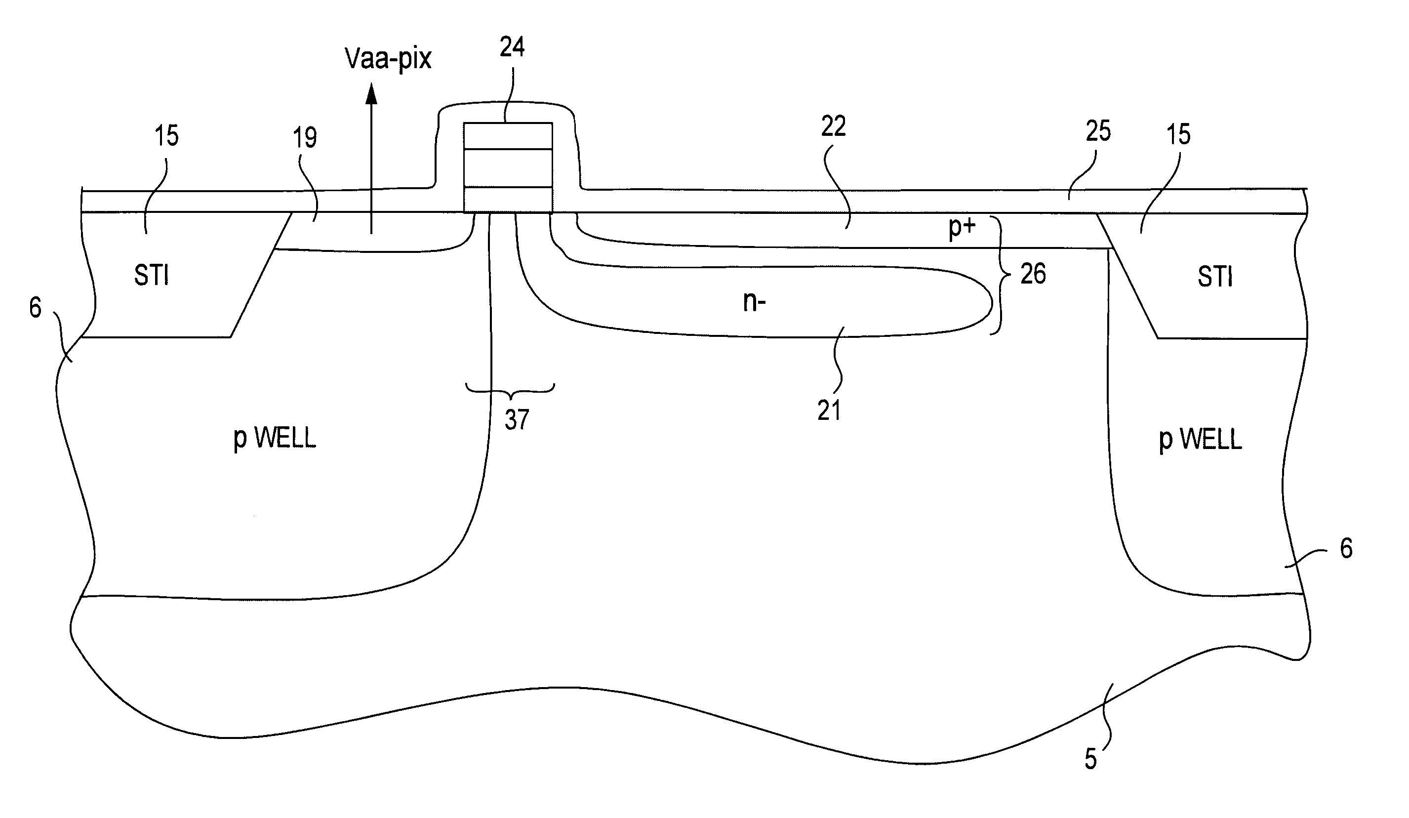
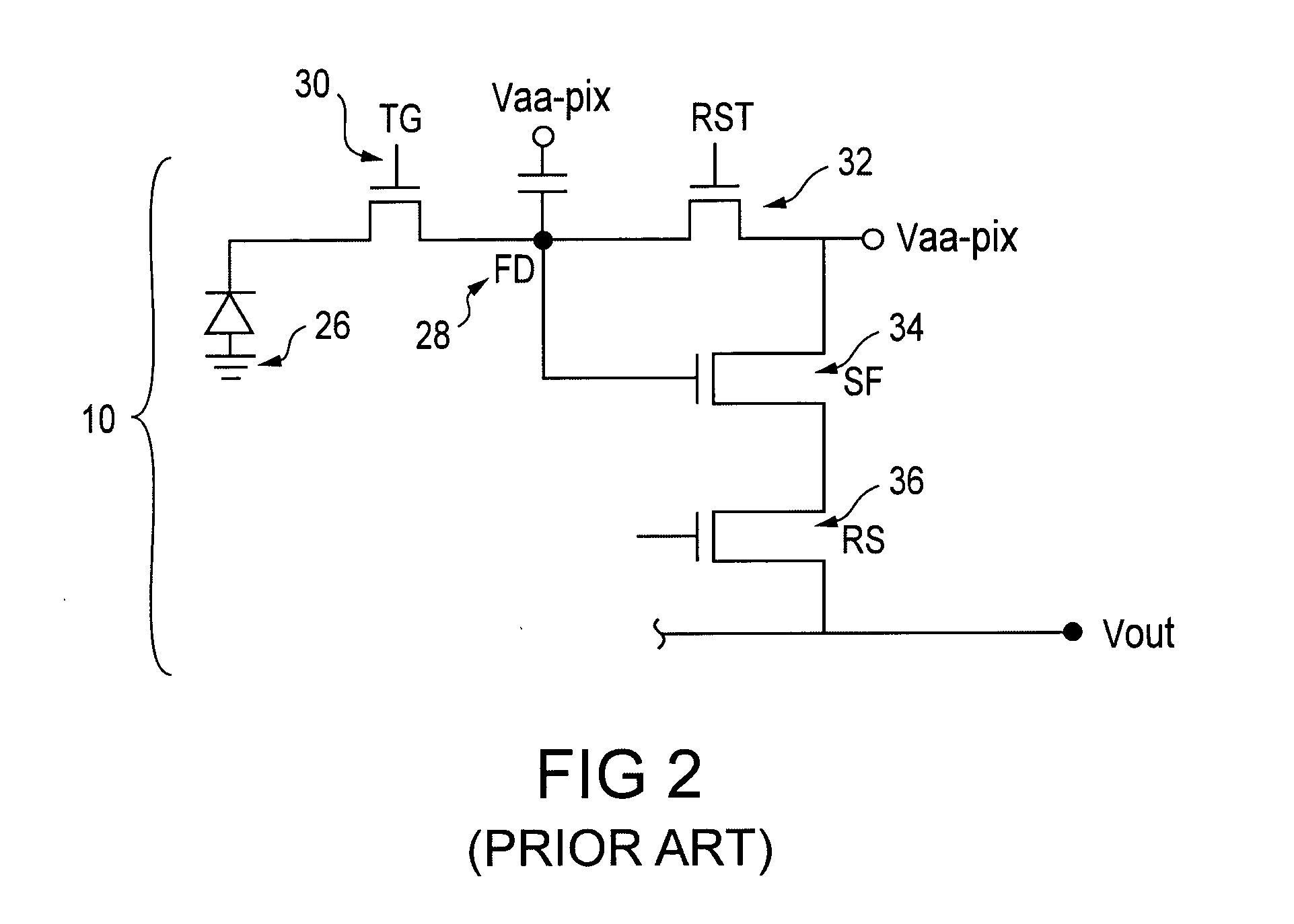
[0011] Embodiments of the present invention provide a pixel cell capable of reaching a higher level of illumination before its maximum output voltage is reached. The pixel cell has controlled photosensor leakage due to an additional transistor in the pixel cell which drains some of the charge generated by the photosensor away from the photosensor during an integration period. This prevents the photosensor from becoming over-saturated and excess charges from overflowing to adjacent pixels.
[0012] The HDR transistor alters the pixel output signal characteristic curve and can increase the dynamic range of the pixel cell.

Problems solved by technology

The electrical dynamic range is limited on an upper end by the charge saturation level of the sensor, and on a lower end by noise imposed limitations and / or quantization limits of the analog to digital converter used to produce the digital image.
A pixel cell's maximum voltage Vmax may be reached at a relatively low level of illumination Imax which causes the pixel cell to be easily saturated, thus limiting the dynamic range of the pixel.
This undesirable phenomenon is known as blooming and results in a bright spot in the output image.

Method used


Image

  • Pixel cell with a controlled output signal knee characteristic response
  • Pixel cell with a controlled output signal knee characteristic response
  • Pixel cell with a controlled output signal knee characteristic response

Examples


Embodiment Construction

[0057] In the following detailed description, reference is made to the accompanying drawings which form a part hereof, and in which is shown by way of illustration specific embodiments in which the invention may be practiced. These embodiments are described in sufficient detail to enable those skilled in the art to practice the invention, and it is to be understood that other embodiments may be utilized, and that structural, logical and electrical changes may be made without departing from the spirit and scope of the present invention.

[0058] The term “substrate” is to be understood as a semiconductor-based material including silicon, silicon-on-insulator (SOI) or silicon-on-sapphire (SOS) technology, doped and undoped semiconductors, epitaxial layers of silicon supported by a base semiconductor foundation, and other semiconductor structures. Furthermore, when reference is made to a “substrate” in the following description, previous process steps may have been utilized to form regio...


PUM


Abstract

A pixel cell with controlled leakage is formed by modifying the location and gate profile of a high dynamic range (HDR) transistor. The HDR transistor may have the gate profile of a transfer gate or a reset gate. The HDR transistor may be located on a side of the photodiode that is the same, opposite to, or perpendicular to the transfer gate. The leakage through the HDR transistor may be controlled by modifying the photodiode implants around the transistor. The photodiode implants at the HDR transistor may be placed similarly to the implants at the transfer gate. However, when the photodiode implants are moved away from the HDR transistor, leakage is reduced. When the photodiode implants are moved farther under the HDR transistor, leakage is increased to the extent desirable. The leakage through the HDR transistor may also be controlled by applying a voltage across the transistor.

Description

FIELD OF THE INVENTION [0001] The present invention relates to the field of semiconductor devices and, in particular, to a pixel cell transistor that improves dynamic range, and provides anti-blooming properties for the cell. BACKGROUND OF THE INVENTION [0002] A CMOS imager circuit includes a focal plane array of pixel cells, each cell includes a photosensor, for example, a photogate, photoconductor or a photodiode overlying a substrate for producing a photo-generated charge in a doped region of the substrate. A readout circuit is provided for each pixel cell and includes at least a source follower transistor and a row select transistor for coupling the source follower transistor to a column output line. The pixel cell also typically has a floating diffusion node, connected to the gate of the source follower transistor. Charge generated by the photosensor is sent to the floating diffusion region. The imager may also include a transistor for transferring charge from the photosensor t...

Claims


Application Information

Patent Timeline
Patent Type & Authority Applications(United States)
IPC IPC(8): H01L31/062
CPCH01L27/14603H01L31/035272H01L27/14689H01L27/14609
Inventor RHODES, HOWARD E.
Owner APTINA IMAGING CORP
Why Eureka
Try Eureka