Switched constant current driving and control circuit

a constant current driving and control circuit technology, applied in the direction of electric variable regulation, process and machine control, instruments, etc., can solve the problems of large power consumption of control circuits, large power devices and heat sinks, and inability to achieve 0 to 100% dimming, etc., to achieve the effect of reducing thermal cycling effects, avoiding excessive power loss, and balancing current distribution

Active Publication Date: 2006-01-05
SIGNIFY HLDG BV
View PDF13 Cites 206 Cited by
  • Summary
  • Abstract
  • Description
  • Claims
  • Application Information

AI Technical Summary

Benefits of technology

[0054] In one embodiment in which multiple light-emitting element strings are to be driven by a single power supply, each light-emitting element string is connected to a voltage converter as illustrated in FIG. 3. Each voltage converter 221, 222 to 223, may be individually switched at a particular frequency, to produce the voltages desired at nodes 201, 202 to 203, respectively, in order to drive light-emitting element loads 241, 242 to 243, respectively. Thus, each light-emitting element string can be switched from a 0 to 100% duty cycle to give essentially the maximum and minimum intensity obtainable by the control signal input via transistors 231, 232 to 233. Therefore all the light-emitting elements can be dimmable down to very low duty cycles as well as being able to emit light at essentially maximum intensity. An advantage of the present invention is that each string can have a different forward voltage yet still have constant current and full dimming without large power losses.
[0055] In one embodiment in which multiple light-emitting element strings require the same voltage supply at the high end of the strings, these light-emitting element strings may have their high ends connected to a single voltage converter. The light-emitting elements may further be connected in a parallel and / or series configuration. FIG. 1f illustrates a plurality of light-emitting elements cross connected in a series-parallel arrangement according to one embodiment of the present invention. This configuration of light-emitting elements can provide better balance the current distribution among the light-emitting elements, for example.
[0056] Furthermore, in one embodiment of the present invention in which multiple light-emitting element strings are to be driven by a single power supply, the phase of one or more frequency signals input to the voltage converters may be phase shifted. FIG. 4a illustrates three signals 41, 42 and 43 that are input to three voltage converters connected to a power supply, wherein these signals are phase shifted relative to one another. FIG. 4b illustrates the total current 44 drawn from the power supply during the input of the signals illustrated in FIG. 4a. FIG. 4c and FIG. 4d illustrate three input signals 45, 46 and 47 that are not phase shifted with respect to each other and the total current 48 output by the power supply, respectively. Phase shifting of these input signals can allow the power supply load to be essentially balanced. In addition, when the voltage converter input signals are phase shifted, the power supply feeding the voltage converters may experience a higher frequency than when the input signals are not phase shifted. Therefore, the output from the power supply may further be filtered from various noise sources at lower frequencies. Dimming Control Means
[0057] Dimming of light-emitting elements is typically done by switching the devices ON and OFF at a rate at which the human eye perceives the light output as an average light level based on the duty cycle rather than a series of light pulses. The relationship between duty cycle and light intensity may therefore be linear over the entire dimming range. As described earlier in relation to FIG. 1a, dimming can be provided using a dimming control signal 140 input via transistor 13. The load can typically be switched at a frequency that is lower than the switching frequency of the voltage converter 12 so that the ripple in the power supply output is averaged out over the time the load is switched ON. Switching the light-emitting elements at a relatively high frequency allows them to be switched at frequencies that are outside the audible range. In addition, switching the load at relatively high frequencies can reduce the effects of thermal cycling on the electronic devices since they are switched ON for a small fraction of time before being switched OFF again.
[0058] Another embodiment of the present invention is shown in FIG. 1b and makes use of a switching device 900 located between the voltage converter 12 and the light-emitting element load 15, which can be a FET, BJT, relay, or any other type of switching device which makes use of an external control input 140 to turn ON or OFF the light-emitting element load 15. As shown in FIG. 1c, this device 900 may alternately be located on the ‘low side’ rather than the ‘high side’, that is, after the light-emitting elements rather than before them.
[0059] In one embodiment in which there are multiple light-emitting element strings driven by a single power supply, each light-emitting element string may have a common dimming control signal, that is, the gates of transistors 231, 232 to 233 may be connected together and to a single dimming signal. In addition, transistors 231, 232 to 233 may also have individual control signals for each light-emitting element string or groups of light-emitting element strings. Sensing Means

Problems solved by technology

A problem with using a linear constant current circuit, however, is that the control circuit dissipates a large amount of power, and consequently requires large power devices and heat sinks.
In addition, when any non-switched constant current system is dimmed, 0 to 100% dimming is typically not achievable.
The problem with these types of designs is that they are inefficient due to the power losses in the biasing resistor, and may require custom resistors to accurately control the current.
U.S. Pat. No. 4,001,667 also discloses a closed loop circuit that provides constant current pulses, however, this circuit does not allow for full duty cycle control over the LEDs.
The problem with this method is that if the low frequency signal is within the range of 20 Hz to 20,000 Hz, as disclosed, the power supply can produce audible noise.
Also, switching frequencies in this range can thermally cycle the LED's thus likely reducing the reliability and lifetime of the device.
The signal controlling the switching of the load is biased such that it operates the switch essentially in its linear region in order to provide peak current control which can result in power losses within the switch, thereby reducing the overall system efficiency.
In addition, this configuration is defined as being applicable for frequencies in the range of 400 Hz and does not allow for high frequency switching of the load for example at frequencies above the 20 kHz which is approximately the audible threshold range.
A problem arises, however when multiple LED strings require different forward voltages.
These high side transistor switches can induce large losses and decrease the overall efficiency of the circuit.
In addition, this circuit does not allow a full range of dimming to be obtained.

Method used


Image

  • Switched constant current driving and control circuit
  • Switched constant current driving and control circuit
  • Switched constant current driving and control circuit

Examples


Embodiment Construction

Definitions

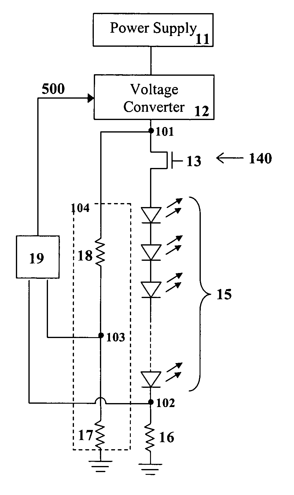
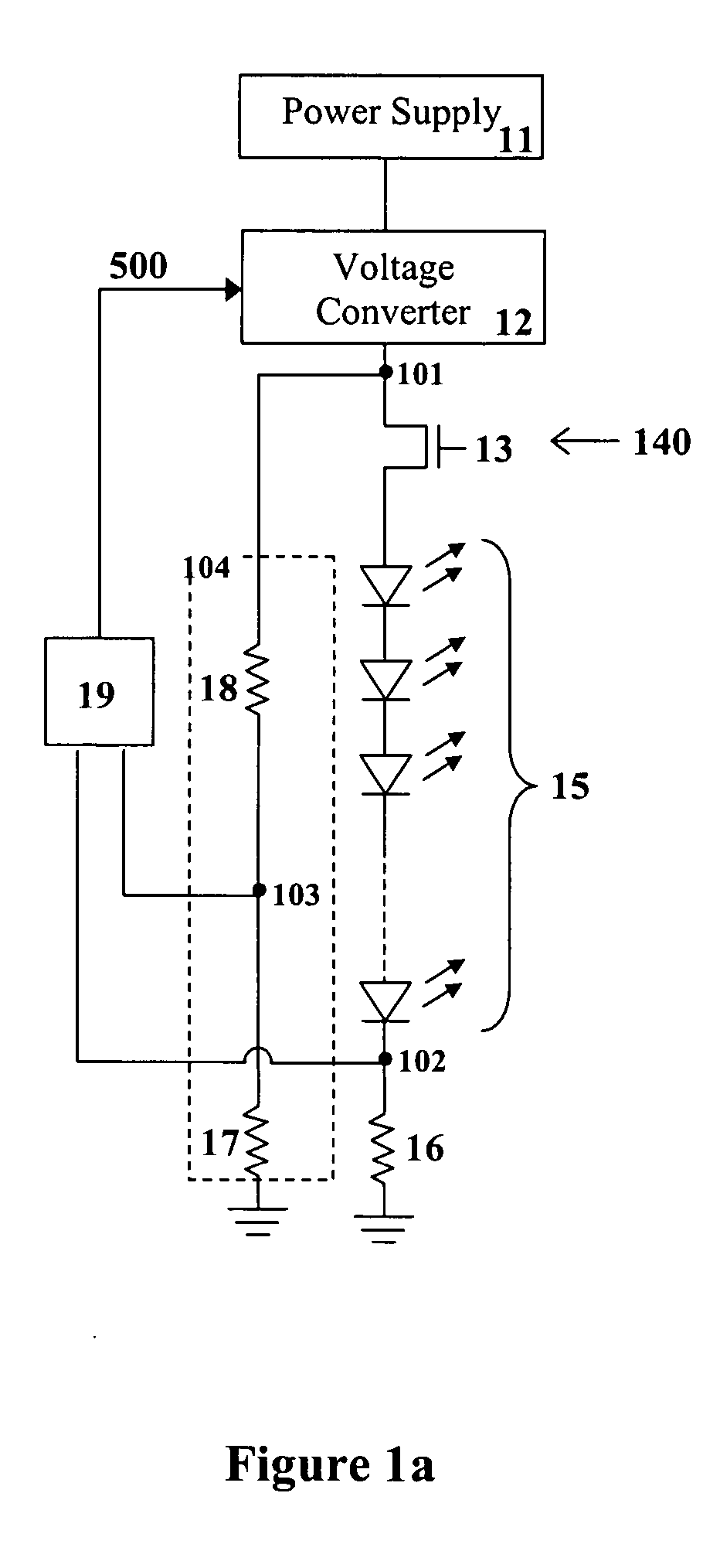
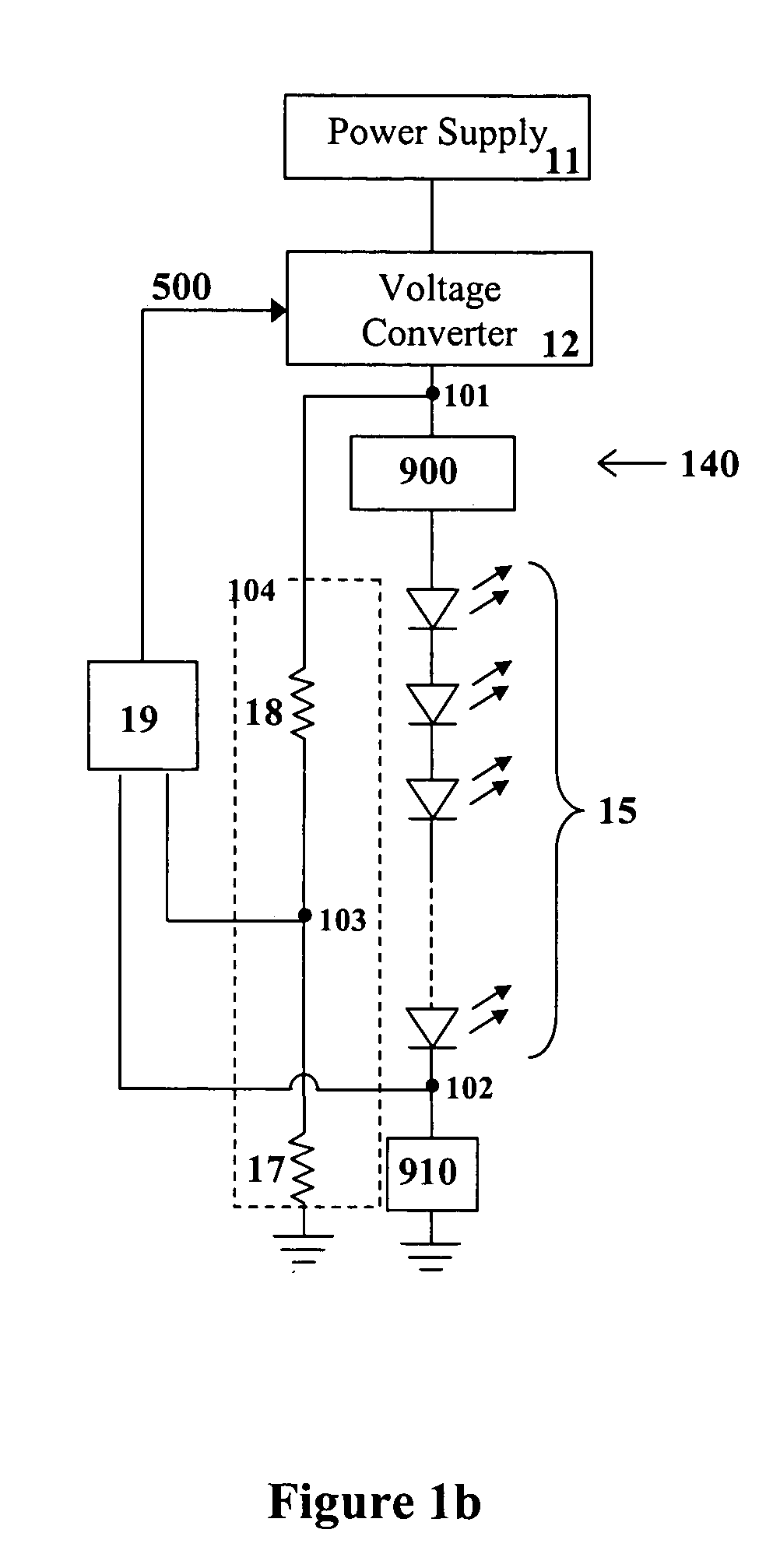
[0037] The term “power supply” is used to define a means for providing power from a power source to electronic circuitry, the power being of a particular type, i.e. AC or DC, and magnitude.

[0038] The power source input to the power supply may be of any magnitude and type, and the output from the power supply may also be of any magnitude and type.

[0039] The term “voltage converter” is used to define a type of power supply that is used to convert an input voltage from one magnitude to an output voltage of another magnitude.

[0040] The term “electronic device” is used to define any device wherein its level of operation is dependent on the current being supplied thereto. Examples of an electronic device includes a light-emitting element, DC motor, laser diode and any other device requiring current regulation as would be readily understood by a worker skilled in the art.

[0041] The term “light-emitting element” is used to define any device that emits radiation in a particu...


PUM


Abstract

The driving and control device according to the present invention provides a desired switched current to a load including a string of one or more electronic devices, and comprises one or more voltage conversion means, one or more dimming control means, one or more feedback means and one or more sensing means. The voltage conversion means may be a DC-to-DC converter for example and based on an input control signal converts the magnitude of the voltage from the power supply to another magnitude that is desired at the high side of the load. The dimming control means may comprise a switch such as a FET, BJT, relay, or any other type of switching device, for example, and provides control for activation and deactivation of the load. The feedback means is coupled to the voltage conversion means and a current sensing means and provides a feedback signal to the voltage conversion means that is indicative of the voltage drop across the current sensing means which thus represents the current flowing through the load. The current sensing means may comprise a fixed resistor, variable resistor, inductor, or some other element which has a predictable voltage-current relationship and thus will provide a measurement of the current flowing through the load based on a collected voltage signal. Based on the feedback signal received, the voltage conversion means can subsequently adjust its output voltage such that a constant switched current is provided to the load.

Description

CROSS-REFERENCE TO RELATED APPLICATIONS [0001] This application claims the benefit under 35 U.S.C. § 119(e) of U.S. Provisional Application No. 60 / 583,607, filed Jun. 30, 2004, and entitled “Switched Constant Current Driving and Control Circuit”, which is hereby incorporated by reference herein in its entirety.FIELD OF THE INVENTION [0002] The present invention pertains to the field of driver circuits, and more particularly, to driver circuits that provide switched constant current sources for electronic devices such as light-emitting elements. BACKGROUND [0003] Recent advances in the development of semiconductor light-emitting diodes (LEDs) and organic light-emitting diodes (OLEDs) have made these devices suitable for use in general illumination applications, including architectural, entertainment, and roadway lighting, for example. As such, these devices are becoming increasingly competitive with light sources such as incandescent, fluorescent, and high-intensity discharge lamps. ...

Claims


Application Information

Patent Timeline
Patent Type & Authority Applications(United States)
IPC IPC(8): H05B37/00H05B44/00
CPCH05B33/0815H05B33/0857H05B33/0818H05B45/46H05B45/3725H05B31/50
Inventor ROBINSON, SHANE P.JUNGWIRTH, PAULTOMA, ION
Owner SIGNIFY HLDG BV
Why Eureka
Try Eureka