
Battery-assisted backscatter RFID transponder

Inactive Publication Date: 2006-01-05
POWERID LTD
View PDF27 Cites 100 Cited by
  • Summary
  • Abstract
  • Description
  • Claims
  • Application Information

AI Technical Summary

Benefits of technology

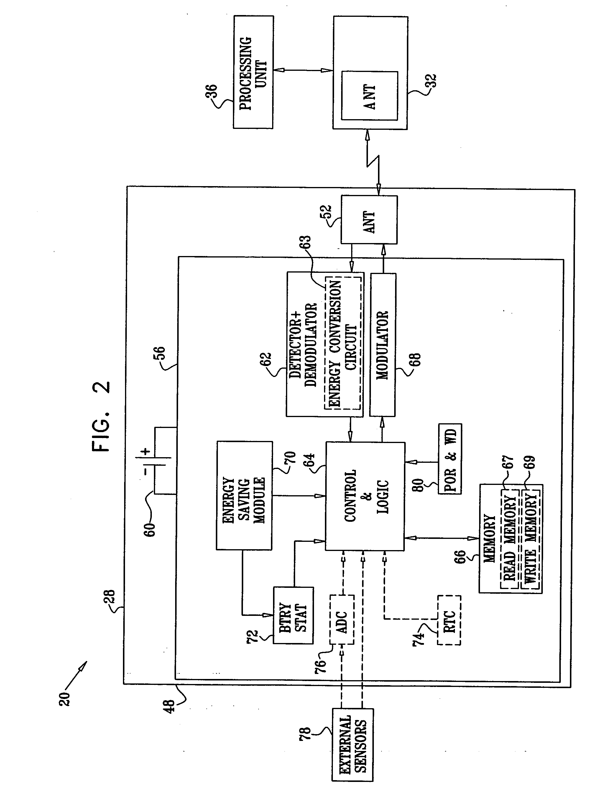
[0005] Battery-assisted backscatter transponders, as described in the background art, can use part of the energy of the received interrogation radiation for powering the transponder circuitry, in parallel to their internal battery. This configuration reduces the amount of energy that is available for backscattering, thus reducing the achievable communication range of the transponder.
[0092] a state machine, which is arranged to detect a presence of RF radiation at the transponder, to analyze signals carried by the detected RF radiation, to progressively activate components of the transponder responsively to the analyzed signals, so as to reduce the energy consumption, to assess a relevance of the RF radiation to the transponder based on the analyzed signals, and, based on the relevance, to enable the transponder to react to the RF radiation; and

Problems solved by technology

This configuration reduces the amount of energy that is available for backscattering, thus reducing the achievable communication range of the transponder.

Method used


Image

  • Battery-assisted backscatter RFID transponder
  • Battery-assisted backscatter RFID transponder
  • Battery-assisted backscatter RFID transponder

Examples


implementation examples

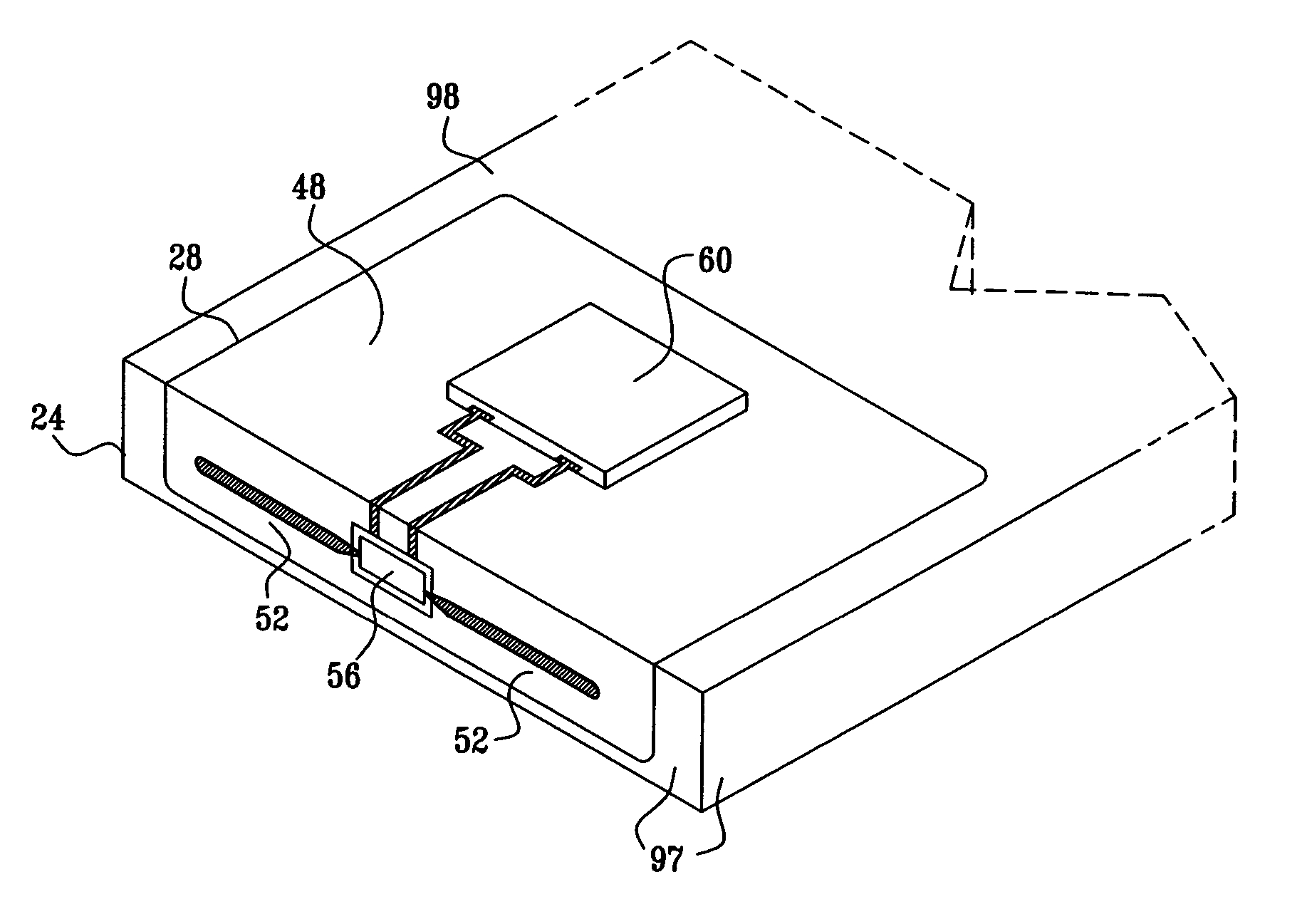
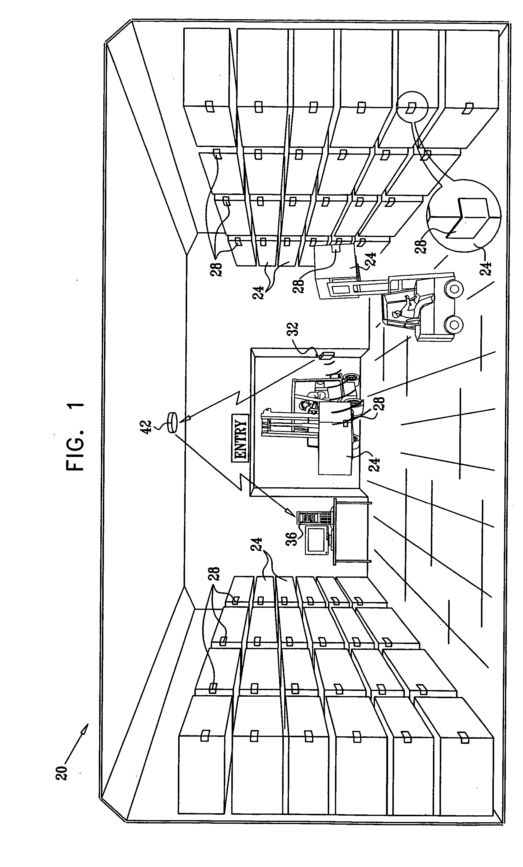
[0251] Reference is now made to the following two examples, which together with the above descriptions illustrate the invention in a non-limiting fashion. The following table provides an exemplary specification of a transponder 28, in accordance with an embodiment of the present invention:

ParameterSpecificationOperating frequency860-880 and 902-928 MHzFrequency hopping operationAs authorized for the readerOptimized antenna RCSσ / λ2 = 1 m2 for a 10 × 10 cmlabel areaOptimized antenna ΔRCSΔσ / λ2 = 0.9 RCSFree space read and write30 mrange with reader effectiveisotropic radiated power(EIRP) = 4 WattReader to transponderASK, DSB, SSB, FSK or PSKmodulationTransponder to readerASK or subcarrier PSKmodulationReader to transponder data4.8-128 kbit / secrateTransponder to reader data4.8-512 kbit / secrateReader to transponder codingNRZ, Miller, PIE or PWMTransponder to reader codingdirect or subcarrier, NRZ,FM0 or MillerBasic non-volatile (EEPROM)memory organization:UID64-196 BitsSystem Memory128...


PUM


Abstract

A radio frequency transponder includes at least one battery, which is coupled to provide electrical power for operating the transponder and at least one antenna, which is configured to receive and backscatter RF interrogation radiation from an interrogation device. An integrated circuit is arranged to store a code including information and, powered only with energy provided by the battery, to vary a radiation characteristic of the antenna responsively to the code so as to modulate the information onto the backscattered radiation.

Description

CROSS-REFERENCE TO RELATED APPLICATIONS [0001] This application claims the benefit of U.S. Provisional Patent Application 60 / 584,141, filed Jul. 1, 2004, of U.S. Provisional Patent Application 60 / 602,342, filed Aug. 18, 2004, of U.S. Provisional Patent Application 60 / 608,118, filed Sep. 9, 2004, of U.S. Provisional Patent Application 60 / 614,552, filed Oct. 1, 2004, and of U.S. Provisional Patent Application 60 / 649,561, filed Feb. 4, 2005. These related applications are assigned to the assignee of the present patent application, and their disclosures are incorporated herein by reference.FIELD OF THE INVENTION [0002] The present invention relates generally to radio frequency identification (RFID) systems, and particularly to battery-assisted backscatter RFID transponders, their components and methods for producing RFID transponders. BACKGROUND OF THE INVENTION [0003] Radio frequency identification (RFID) systems are used in a variety of applications, ranging from warehouse inventory c...

Claims


Application Information

Patent Timeline
IPC IPC(8): H04Q5/22G08B13/14
CPCG06K19/0702G06K19/0705G06K19/0707G06K19/0712H01Q9/16G06K19/07749H01Q1/22H01Q1/2225H01Q1/38G06K19/0723G06K19/07G06K17/00H01Q1/24H04B5/48
Inventor NITZAN, ZVILAVEE, DORONGURI, GABY
Owner POWERID LTD
Learn More