Light source apparatus and image projection apparatus

a technology of light source apparatus and image, which is applied in the direction of lighting and heating apparatus, static indicating devices, instruments, etc., can solve the problems of insufficient color rendering performance, insufficient improvement of luminance and efficiency of video light, and limited to certain specific products, etc., to achieve easy to radiate heat and reduce the effect of heat generation

Inactive Publication Date: 2006-01-05
OLYMPUS CORP
View PDF1 Cites 63 Cited by
  • Summary
  • Abstract
  • Description
  • Claims
  • Application Information

AI Technical Summary

Benefits of technology

[0045] Preferably, the image projection apparatus further comprises a cooling unit for expelling heat generated by the lamp and the LED light source unit from the apparatus, wherein the cooling unit expels the heat via a first channel

Problems solved by technology

Some of these discharge-type lamps, for example, xenon lamps, are light sources extremely excellent in color rendering properties but limited to certain specific products due to high cost and a large lamp size.
In general, an extra-high pressure mercury lamp is mainly used as a white-light source of an image projection apparatus and is now used widely, which is, however, not expect

Method used


Image

  • Light source apparatus and image projection apparatus
  • Light source apparatus and image projection apparatus
  • Light source apparatus and image projection apparatus

Examples


first embodiment

[0092] Next, the light source apparatus and the image projection apparatus of the invention will be described with reference to FIG. 1 to FIG. 9.

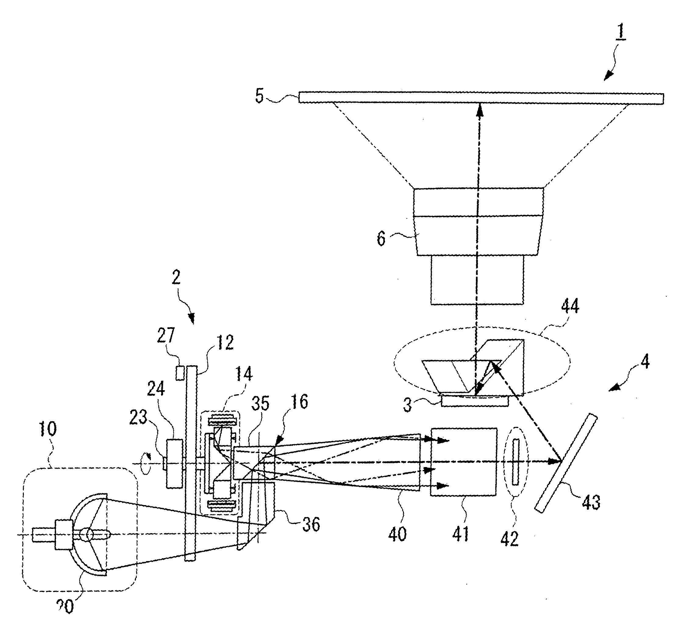
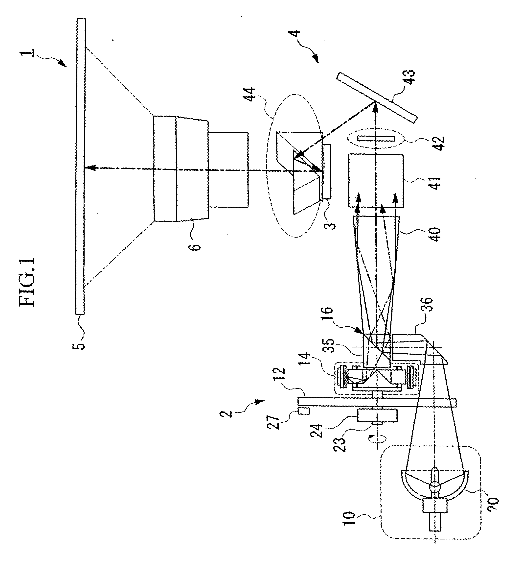
[0093] An image projection apparatus 1 of this embodiment intends to project an image so that an observer can observe the image according to the image information to be input, and, as shown in FIG. 1, comprises a light source apparatus 2, a DMD (Digital Micro-mirror Device; registered trade mark) (spatial modulation element) 3, modulated according to image information to be input, a illuminating optical unit 4 for guiding illumination light emitted from a synthetic prism 16 (an optical synthesis unit) of the light source apparatus 2 to be described later and illuminating the DMD 3 and a projection lens (optical projection unit) 6 for projecting on the screen 5 an image projected by the illuminating optical unit 4 and modulated by the DMD 3.

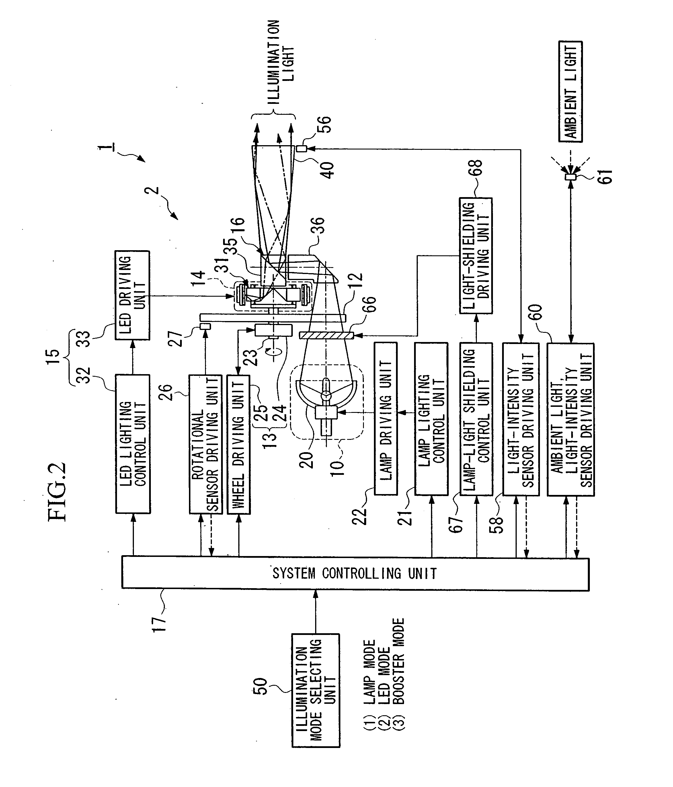
[0094] As shown in FIG. 2, the above light source apparatus 2 comprises a lamp 10 emitting white illu...

embodiment 1

[0168] Further, in the above embodiment 1, it is structured so that an observer can select three modes by using the illumination-mode selecting unit 50, but the present invention is not restricted thereto. For example, such a structure may be acceptable that when an ambient light intensity detected is smaller than a predetermined value, the LED mode is automatically selected, and when it is greater than the predetermined value, the booster mode is automatically selected.

[0169] To be more specific, as shown in FIG. 2 and FIG. 10, the image projection apparatus 1 is provided with an ambient light intensity sensor 61 for detecting the light intensity of ambient light controlled by an ambient light intensity sensor driving unit 60. Further, the illumination-mode selecting unit 50 is provided with an automatic mode SW 62 for automatically switching between the booster mode and the LED mode, and the system controlling part 17 is provided with a light source selecting unit 63 which actuate...

second embodiment

[0220] To be more specific, as shown in FIG. 23 and FIGS. 24A and 24B, a light source apparatus 81 of the this embodiment is provided with a luminescence chip 83 fixed on a heat conducting block 82 at the same position where the light guide unit 31 of the second embodiment is located. The luminescence chip 83 is electrically connected to an electric pole 85 fixed to the heat conducting block 82 via a package 84. The luminescence chip 83 is designed to emit red (R) illumination light when electric power is supplied to an electrode 85 via the LED driving unit 33. A light conductive resin 86 is provided between the luminescence chip 83 and the taper rod 72 so that illumination light emitted from the luminescence chip 83 is reliably made incident on the taper rod 72.

[0221] In addition, the LED lighting control unit 32 controls the luminescence chip 83 so that the chip is turned on at the timing when the red (R) portion of the color filter 11 of the color wheel 12 reaches a position wher...


PUM


Abstract

The present invention provides a light source apparatus and an image projection apparatus having the light source apparatus. The light source apparatus includes a lamp for emitting white illumination light, a color wheel for sequentially switching a color filter on which illumination light emitted from the lamp is incident, a wheel driving unit for controlling rotation of the color wheel, an LED light source unit for emitting at least one color of illumination light, an LED driving unit for controlling illumination light of the LED light source unit, an optical synthesis unit capable of optically synthesizing illumination light from the lamp and illumination light from the LED light source unit and emitting such synthesized illumination light, and a system controlling unit for controlling the wheel driving unit and the LED driving unit so that each illumination light synthesized can be the same in color.

Description

PRIORITY CLAIM [0001] Priority is claimed on Japanese Patent Application No. 2004-192909, filed Jun. 30, 2004, the content of which is incorporated herein by reference. BACKGROUND OF THE INVENTION [0002] 1. Field of the Invention [0003] The present invention relates to a light source apparatus having mode selecting functions for giving priority to the color reproduction of a display image or to brightness according to need, and to an image projection apparatus having the light source apparatus. [0004] 2. Description of the Related Art [0005] Known conventional image projection apparatuses include a type in which a white-light source is used to produce light separated into primary colors of red (R), green (G) and blue (B), and another type in which an optical semiconductor, for example, one capable of naturally emitting light of primary colors such as a light-emitting diode (LED), is used. [0006] In the above-described image projection apparatus in which a white-light source is used,...

Claims


Application Information

Patent Timeline
IPC IPC(8): F21V9/00
CPCH04N9/3114H04N9/315H04N9/3197H04N9/3158H04N9/3164H04N9/3155
Inventor IMADE, SHINICHI
Owner OLYMPUS CORP
Why Eureka
Try Eureka