Bearing unit for wheel and method of manufacturing the bearing unit

a technology of bearing unit and wheel, which is applied in the field of wheel bearing unit, can solve the problems of difficult to make a complete right angle, and the sensing performance of the rotation speed sensor becomes worse, so as to improve the dimensional accuracy of a plurality of parts, the cost required to suppress the swing of the braking friction surface can be sufficiently low, and the effect of reducing the number of parts

Active Publication Date: 2006-01-05
NSK LTD
View PDF5 Cites 32 Cited by
  • Summary
  • Abstract
  • Description
  • Claims
  • Application Information

AI Technical Summary

Benefits of technology

[0039] In addition, according to the wheel bearing unit set forth in claim 2 and a method of manufacturing the wheel bearing unit set forth in claim 5, when the braking friction surface of the braking rotation body is processed in the predetermined shape and dimension, such an event can be eliminated that the dimensional error or the assembling error that is inevitable in manufacturing a plurality of parts that are located between a part of the suspension system and the braking rotation body leads to the worsening of a perpendicularity or a parallelism of the braking friction surface to a center of rotation of the rotating shaft. Therefore, the swing of the braking friction surface can be suppressed sufficiently. Also, since there is no necessity to improve particularly a dimensional accuracy of a plurality of parts, a cost required to suppress the swing of the braking friction surface can be suppressed sufficiently low.

Problems solved by technology

Meanwhile, it is known that the vibration called the shudder that entails an unpleasant noise is often generated in the braking operation of the car.
In other words, the side surface of the rotor 2 must be set essentially at a right angle to a center of rotation of the rotor 2, nevertheless it is difficult to make a complete right angle due to the inevitable manufacturing error, and so on.
For this reason, a following disadvantage ① is caused when the encoder is provided to the wheel bearing unit set forth in above Patent Literatures 1, 2.
In case the chips adhere in this manner, a sensing performance of the rotation speed sensor becomes worse in the wheel bearing unit into which the rotation speed sensing device is incorporated.
② First, in the case of the configuration set forth in above Patent Literature 1, there exists the dimensional error or the assembling error that is inevitable in manufacturing between the side surface of the rotary flange provided to the outer peripheral surface of the hub and the side surface of the braking rotation body such as the rotor, or then like fixed to this side surface.
Therefore, it is difficult to say that the swing of the braking friction surface of the braking rotation body can be suppressed satisfactorily.
Then, in the case of the method of manufacturing the wheel bearing unit set forth in above Patent Literature 2, there exists the dimensional error or the assembling error that is inevitable in manufacturing a plurality of parts that are located between the knuckle constituting the suspension system and the portion, on which the inner ring is fitted, of the outer peripheral surface of the hub.
Therefore, it is also difficult to say that the swing of the side surface of the braking rotation body can be suppressed satisfactorily.
However, in this Patent Literature 3, a method of manufacturing the wheel bearing unit in which a degree of instability of the side surface is regulated is not set forth at all.

Method used


Image

  • Bearing unit for wheel and method of manufacturing the bearing unit
  • Bearing unit for wheel and method of manufacturing the bearing unit
  • Bearing unit for wheel and method of manufacturing the bearing unit

Examples


first embodiment

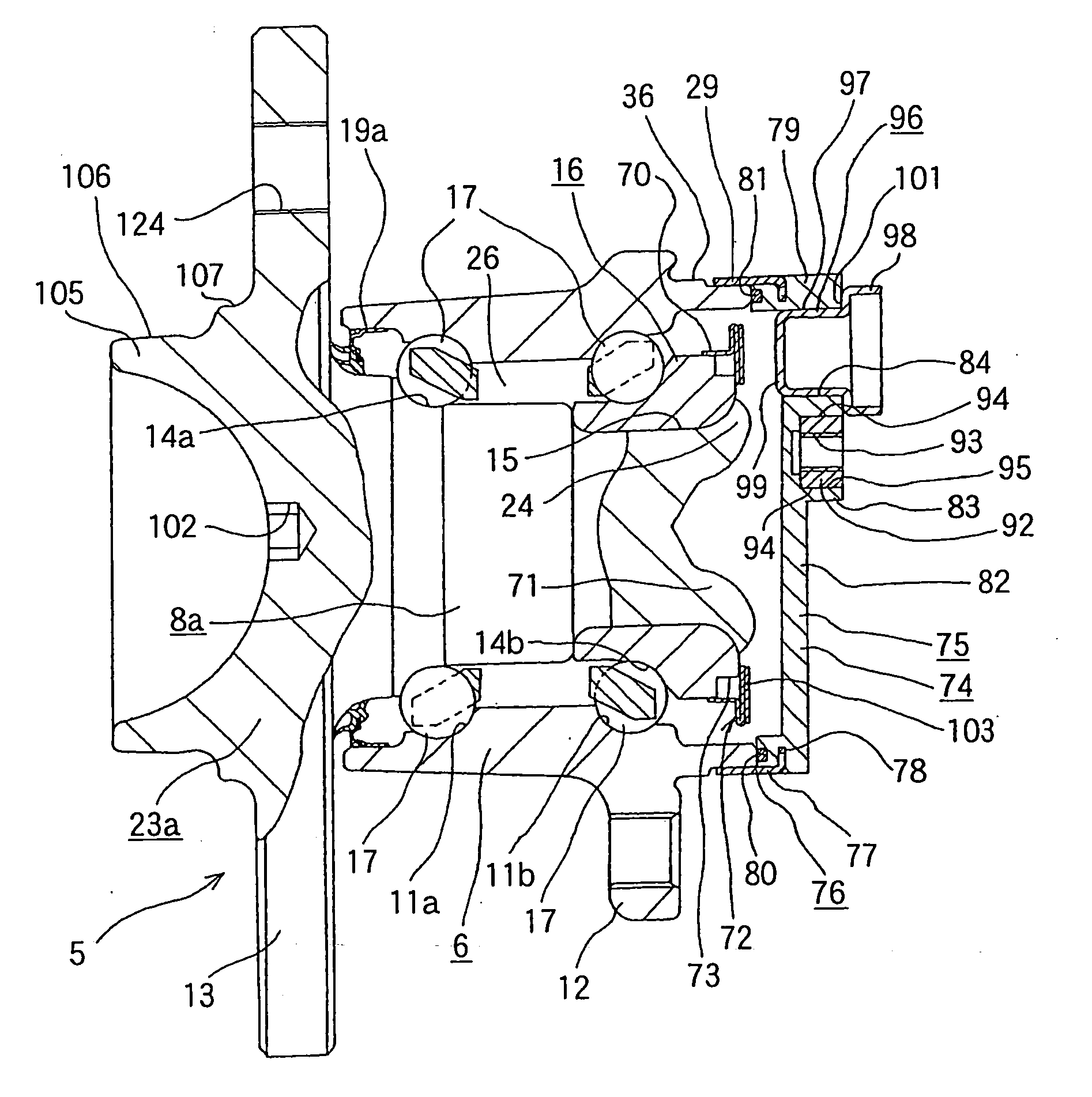
[0062] FIGS. 1 to 4 show the present invention, which corresponds to claims 1, 3, 4, and 6. In the wheel bearing unit 5 produced by the manufacturing method in this example, the stationary flange 12 used to couple / fix the outer ring 6 to the knuckle 3 (see FIG. 21) is provided to the middle portion of the outer peripheral surface of the outer ring 6 as the stationary ring. Also, the double row outer ring raceways 11a, 11b serving as the stationary side raceway respectively are formed on the inner peripheral surface as the stationary peripheral surface of the outer ring 6. Also, a small-diameter stepped portion 29 is formed on an inner half portion, which is deviated inward from the inner side surface of the stationary flange 12, of the outer peripheral surface of the outer ring 6.

[0063] Also, the inner ring raceways 14a, 14b serving as the rotary raceway respectively are formed on portions, which oppose to the outer ring raceways 11a, 11b, of the outer peripheral surfaces as the rot...

second embodiment

[0101] Since other structures and operations are similar to those in the second embodiment shown in above FIGS. 5 to 7, their redundant explanation will be omitted herein by affixing the same reference numerals to like portions respectively.

[0102] Next, FIG. 10 shows a fourth embodiment of the present invention, which also corresponds to claims 1, 3, 4, and 6. In the case of the present embodiment, unlike the third embodiment shown in above FIGS. 8 and 9, a pair of inner rings 16a, 16b are fitted / fixed onto the middle portion and the inner end portion of the outer peripheral surface of the hub 8b in the axial direction respectively. Also, the inner ring raceways 14a, 14b are formed on outer peripheral surfaces of these inner rings 16a, 16b respectively. Also, a pair of seal rings 19a, 19b for sealing tightly the internal space 26 in which a plurality of balls 17, 17 are provided are provided between the outer peripheral surfaces of the end portions of the inner rings 16a, 16b and th...

third embodiment

[0107] Since other structures and operations are similar to those in the third embodiment shown in above FIGS. 8 and 9, their redundant explanation will be omitted herein by affixing the same reference numerals to like portions respectively.


PUM

PropertyMeasurementUnit
diameteraaaaaaaaaa
inner diameteraaaaaaaaaa
forceaaaaaaaaaa

Abstract

Respective constituent members of a wheel bearing unit 5 are assembled and also a cover 74 is fixed to an inner end portion of an outer ring 6. The wheel bearing unit 5 is fitted to a turning machine 38 in a state that a space in which an encoder 72 is provided is sealed tightly from an outside by fitting a stop plug 96 into an insertion hole 84 provided in the cover 74. A top end portion of a rotating shaft 40 of a turning machine 38 is engaged with an engaged concave portion 102 provided to a hub 8a. A turning process is applied to an outer side surface of a rotary flange 13 while turning the hub 8a around the outer ring 6 by the rotating shaft 40, and thus the outer side surface is processed in predetermined shape and dimension.

Description

TECHNICAL FIELD [0001] The present invention relates to a wheel bearing unit for supporting rotatably a wheel on a suspension system in a state that such bearing unit bears and fixes a braking rotation body such as a rotor, a drum, or the like, and improvements in a method of manufacturing such wheel bearing unit. BACKGROUND ART [0002] According to a configuration shown in FIG. 21, for example, a wheel 1 constituting a wheel of a car and a rotor 2 constituting a disc brake as a braking system are supported rotatably on a knuckle 3 constituting a suspension system. More particularly, an outer ring 6 as a stationary ring, which constitutes a wheel bearing unit 5, is fitted into a circular bearing hole 4 formed in the knuckle 3 and then fixed by a plurality of bolts 7. Meanwhile, the wheel 1 and the rotor 2 are coupled / fixed to a hub 8, which constitutes the wheel bearing unit 5, by a plurality of studs 9 and nuts 10. [0003] Double row outer ring raceways 11a, 11b serving as a stationa...

Claims


Application Information

Patent Timeline
Patent Type & Authority Applications(United States)
IPC IPC(8): F16C41/04F16C32/00B23B5/02B60B27/00F16C33/72F16C33/76G01P3/44G01P3/487
CPCB23B5/02B60B27/00F16C33/723F16C33/76F16C41/04Y10T29/49536G01P3/487F16C41/007F16C19/184F16C2326/02G01P3/443
Inventor MITSUE, NAOKISAKAMOTO, JUNSHINAKAMURA, YUJI
Owner NSK LTD
Why Eureka
Try Eureka