Greater angle and overhanging materials deposition

a technology of material deposition and angle, applied in the field of material deposition, can solve the problems of inability to make very complex parts of solid, hollow, or latticed construction, and the process then was very inaccurate, and achieve the effect of convenient collection

Inactive Publication Date: 2006-01-05
OPTOMEC DESIGN CO
View PDF45 Cites 148 Cited by
  • Summary
  • Abstract
  • Description
  • Claims
  • Application Information

AI Technical Summary

Benefits of technology

[0019] An advantage of the present invention is that powder impinging on the surface of the melt pool can collect more easily due to the greater angles of powder entry.
[0020] Another advantage of the present invention is that an annular ring, a multiple nozzle housing assembly, and the additional discrete nozzles can all be used on the same system.
[0021] Yet another advantage of the present invention is that overhangs can be fabricated on any side of (i.e. 360° around) a part.
[0022] A further advantage of the present invention is that due to the greater angle, complex geometries with overhangs up to approximately 180° can be fabricated in a single step usin

Problems solved by technology

The process then was very inaccurate, and the choice of materials was limited.
Moreover, there is a potential for making very complex parts of solid, hollow, or latticed construction.
However, these technologies are limited in their applications of overhangs and angles in fabricated articles.
Pratt further teaches that an angle of greater than about 60 degrees makes it difficult for the nozzle and powder to avoid premature interaction with the laser beam, and less than about 35 degrees makes it difficult to deliver the powder concurrently with the laser beam at the spot desired on the article surface.
However, such overhangs are of minimal application in the indus

Method used


Image

  • Greater angle and overhanging materials deposition
  • Greater angle and overhanging materials deposition
  • Greater angle and overhanging materials deposition

Examples


Embodiment Construction

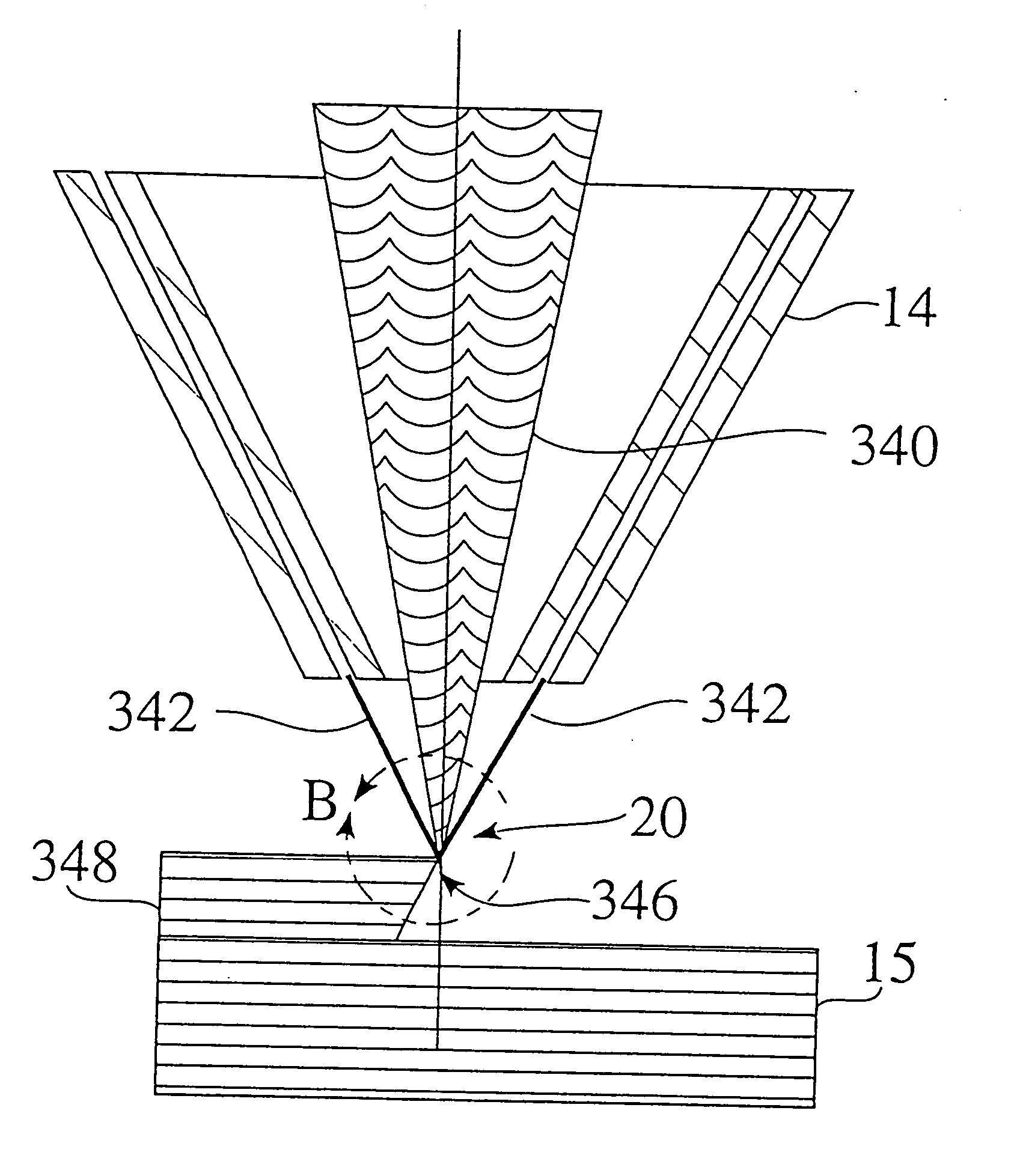
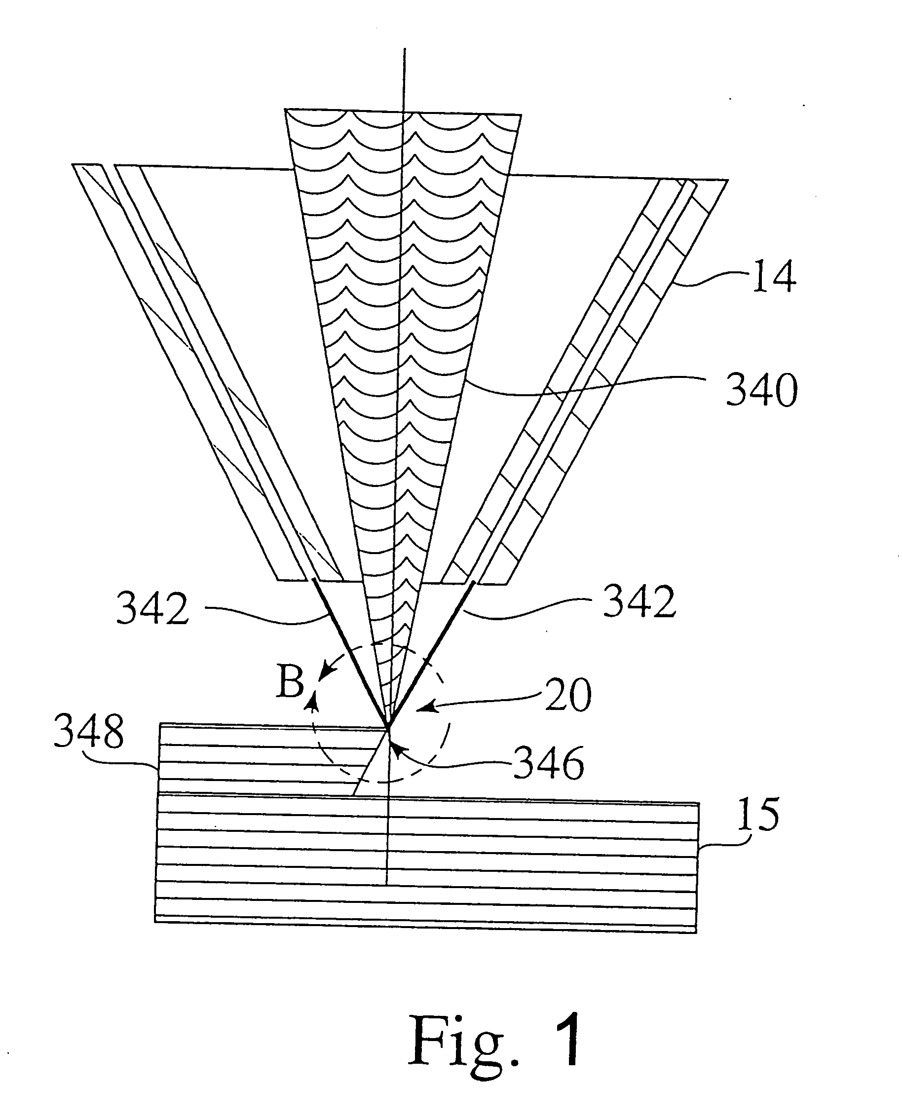
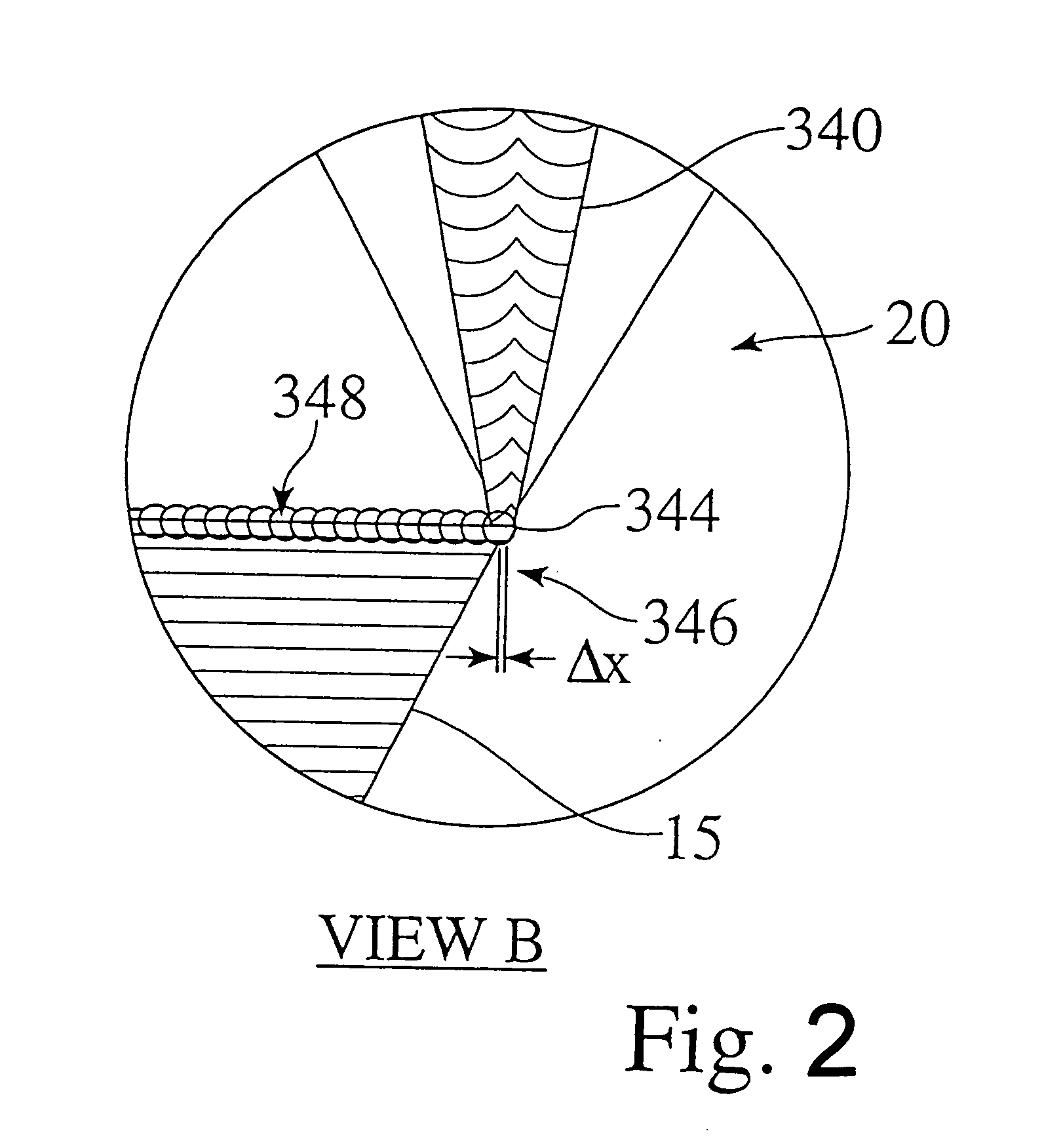
[0040] The LENS® system dispenses metals in patterns preferably dictated by three-dimensional CAD models. Guided by these computerized blueprints, the system creates material structures by depositing them, preferably one layer at a time. The system preferably uses a laser, such as a high-powered Nd:YAG laser, to strike a target and produce a preferably molten pool. Through a deposition head, a nozzle then preferably propels a precise amount of powdered metal into the pool to increase the material volume. A layer is built to the CAD geometric specifications as the positioning system moves the target under the laser beam in the X-Y plane. The lasing and powder-deposition process repeats until the layer is complete. The LENS® system then refocuses the laser in the Z direction, normal to the target, until the unit builds layer upon layer and completes the material version of the CAD model. The standard mode of operation includes 2.5 axes of motion, computer control, a controlled atmosph...


PUM

PropertyMeasurementUnit
Fractionaaaaaaaaaa
Angleaaaaaaaaaa
Angleaaaaaaaaaa

Abstract

Apparatuses and methods for producing greater angle or overhanging deposits on a structure. Nozzles for propelling powder at a target or structure for subsequent laser processing are preferably at a greater angle of powder entry than currently used. The nozzles are arranged around the laser beam and can be individual or disposed around an annular ring. The individual nozzles can be interchangeable with the annular ring. Discrete nozzles can be used in addition to or in place of the other nozzles, allowing angles of powder entry up to approximately 180°. The nozzles may be translated or rotated with respect to the target along or about multiple axes. Also a method for temporarily supporting an overhang using weaker material under the overhang. The weaker material can be removed after the overhang is fabricated and solidified.

Description

CROSS-REFERENCE TO RELATED APPLICATIONS [0001] This application claims the benefit of the filing of U.S. Provisional Patent Application Ser. No. 60 / 567,982, entitled “High Angle Deposition Nozzles and Overhang Support Structures,” filed on May 4, 2004. This application is also a continuation-in-part application of U.S. patent application Ser. No. 10 / 980,455, entitled “Powder Feeder for Material Deposition Systems,” filed on Nov. 2, 2004, which is a continuation application of U.S. patent application Ser. No. 10 / 128,658, now U.S. Pat. No. 6,811,744, entitled “Forming Structures from CAD Solid Models,” filed on Apr. 22, 2002, which is a continuation-in-part application of U.S. patent application Ser. No. 09 / 568,207, now U.S. Pat. No. 6,391,251, entitled “Forming Structures from CAD Solid Models,” filed on May 9, 2000, which claims the benefit of the filing of U.S. Provisional Patent Application Ser. No. 60 / 143,142, entitled “Manufacturable Geometries for Thermal Management of Complex ...

Claims


Application Information

Patent Timeline
IPC IPC(8): B05D5/00
CPCB22F3/004B22F3/1055B23K26/1411B22F2003/1058C23C4/12C23C24/10B23K26/147B23K26/144Y02P10/25B22F10/43B22F12/53B22F12/55B22F10/66B22F10/25B22F12/41B22F10/32
Inventor BULLEN, JAMES L.KEICHER, DAVID M.
Owner OPTOMEC DESIGN CO
Why Eureka
Try Eureka