Radiant burner

a technology of infrared burner and radiant, which is applied in the direction of capillary burner, combustion type, lighting and heating apparatus, etc. it can solve the problems of limited life, limited diameter of wire from which the screen is woven, and limit the strength and resistance to thermal fatigue. , to achieve the effect of restricting flashback, reducing the amount of heat that reaches the plenum, and being durabl

Active Publication Date: 2006-01-05
CHAR BROIL
View PDF79 Cites 96 Cited by
  • Summary
  • Abstract
  • Description
  • Claims
  • Application Information

AI Technical Summary

Benefits of technology

[0018] In accordance with one aspect of the present invention, there can be multiple mounting members (e.g., plates) that play a role in defining the chambers respectively between the perforated members. Each of the mounting members can have holes that extend therethrough, and the holes of the mounting members can be larger than the perforations of the perforated members. Each of the perforated members can be sandwiched between respective mounting members, with the perforations of the perforated member(s) being respectively aligned with, and in communication with, the holes of the mounting members. Advantageously, these sandwich-like articles can be very sturdy and durable.
[0019] Whereas only a single perforated member, or the like, can be used, it can be advantageous to use multiple of them arranged in series in the flow path, in an effort to advantageously restrict flashback and/or advantageously restrict the amount of heat that reaches the plenum

Problems solved by technology

Experience with using these types of burners indicates that they have limited life due to failure of the screen.
Failure of the screen allows the flame to retrogress into the burner plenum resulting in flashback.
Stress developed during the weaving process probably contributes to these failures.
Therefore, the diameter of the wire from which the screen is woven is limited.
The small diameter of the wire limits the strength and resistance to thermal fatigue.
When these types of burners operate on a generally continuous basis, frequent replacement of failed burners is required.
This concept of generating infrared radiant energy is not as efficient as the surface combustion type of infrared burners.
There are some limitations associated with each type of gas-fired radiant burner presently in use.
However, because the emitter surface is made from ceramic, these types of burners are fragile compared to metal.
Also, the ceramic emitter is subject to failure if it is used in applications where it can become wet, such as in outdoor gas grills as described in U.S. Pat. No. 4,321,857 to Best.
Also, when these types of burners are over fired, incomplete combustion can occur.
Burners that use an emitting surface that employs a woven screen have not been reliable and usually have limited life in most applications of continuous use or where the burner is exposed to thermal shock through cycles of heating and cooling.
Both the metal screen burner and ceramic type burners can fail when the input of fuel is incr

Method used


Image

  • Radiant burner
  • Radiant burner
  • Radiant burner

Examples


Embodiment Construction

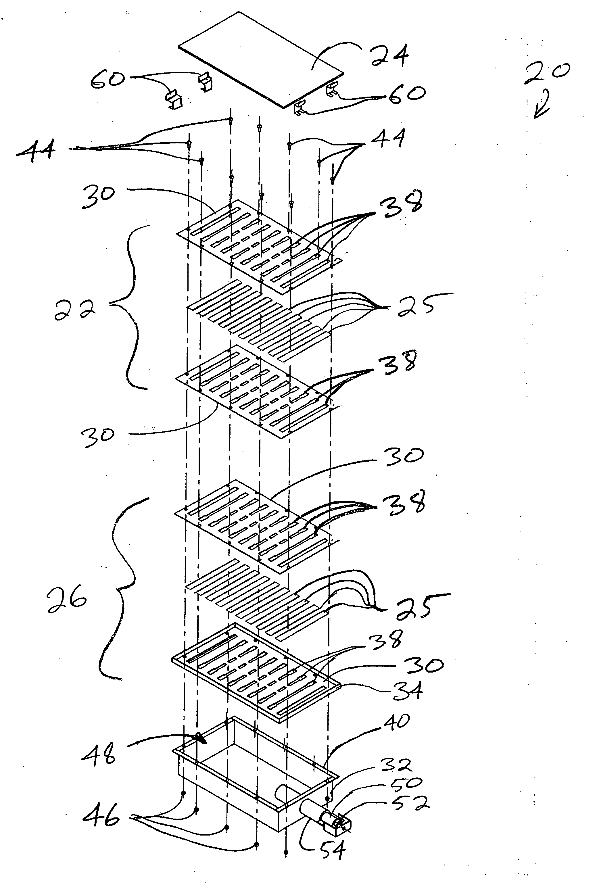
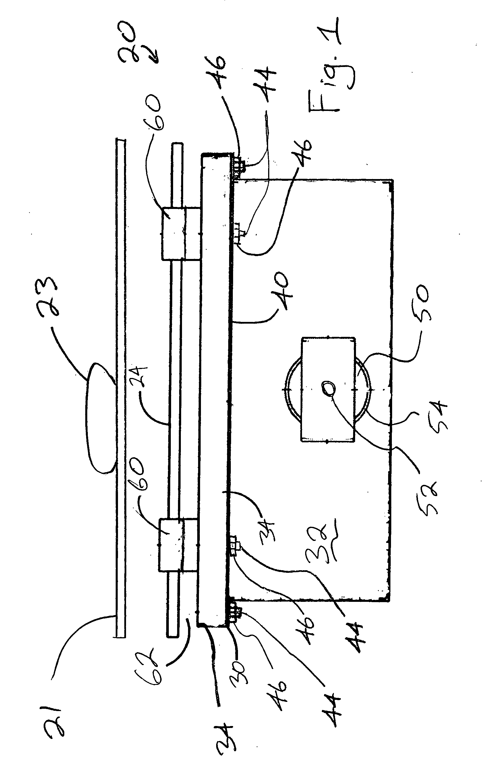
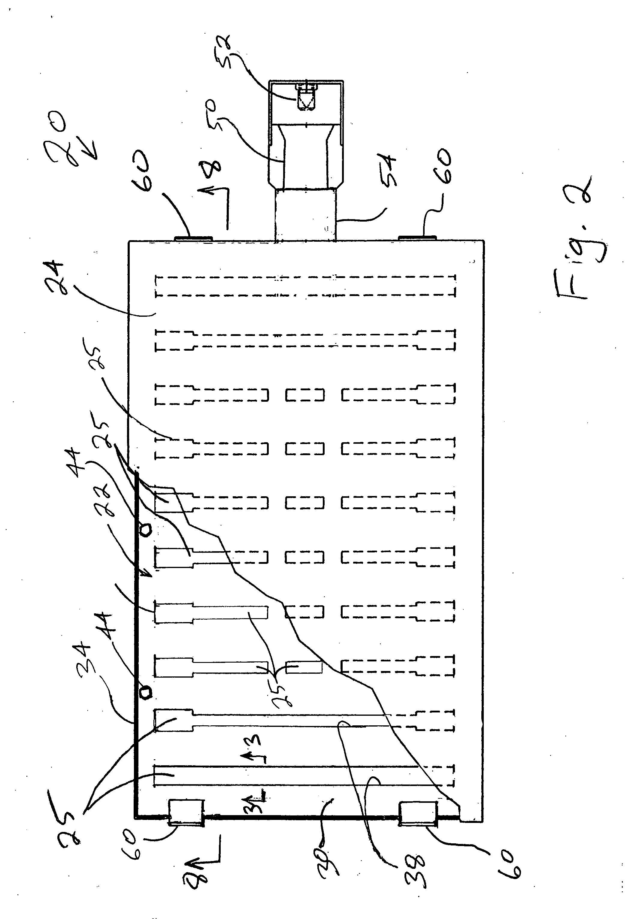
[0044] Referring now in greater detail to the drawings, in which like numerals refer to like parts throughout the several views, FIGS. 1-8 illustrate features of an infrared radiant burner unit 20 for generating infrared radiant energy by burning a gaseous fuel, in accordance with an exemplary embodiment of the present invention. Very generally described, and as can be understood from FIGS. 1-3, the burner unit 20 operates by burning the gaseous fuel so that combustion, which is schematically represented as flames by the series of vertical arrows in FIG. 3, emanates from / is proximate an outer surface of a burner element (e.g., burner assembly 22) and is typically at least partially within a gap between the burner assembly and an infrared radiant energy emitter 24. The vertical arrows in FIG. 3 are schematic in nature because, for example, the flames of the combustion are typically in a bed-like arrangement that is in close proximity to the outer surface of the burner assembly 22 dur...


PUM


Abstract

A gas-fired burner unit for providing combustion and infrared radiation includes at least one plenum for receiving at least the gas, and at least one perforated metal plate mounted for receiving at least the gas from the plenum and supplying at least the gas to the combustion so that the combustion is proximate the perforated metal plate.

Description

CROSS-REFERENCE TO RELATED APPLICATIONS [0001] The present application claims the benefit of both U.S. Provisional Application No. 60 / 582,276, filed Jun. 23, 2004, and U.S. Provisional Application No. 60 / 591,215; filed Jul. 26, 2004. Each of the above-referenced provisional applications is incorporated herein by reference, in its entirety. Also incorporated herein by reference, in its entirety, is the U.S. utility patent application that is entitled “Infrared Emitting Element”, names Willie H. Best as the inventor, and has been filed on the same day as the present application.TECHNICAL FIELD [0002] The present invention relates to gas-fed infrared burners and, more particularly, to partitions used in gas-fed infrared burners. BACKGROUND OF THE INVENTION [0003] There are several types of gas-fired infrared burners being used in various manufactured products. These burners usually incorporate one of three design features. The most used and successful burner design employs a ceramic pl...

Claims


Application Information

Patent Timeline
IPC IPC(8): F23D14/12F23D14/14
CPCA23L1/0128A47J37/0676A47J37/0682F23D14/14F23D2900/14123F23D2203/1026F23D2203/106F23D2212/20F23D2203/1023A23L5/15F23D14/147
Inventor BEST, WILLIE H.
Owner CHAR BROIL
Why Eureka
Try Eureka