Automated fluid flow control system

a fluid flow control and automatic technology, applied in the field of intravenous infusion therapy, can solve the problems of low reliability of human operators to accurately compute flow rate, method is critically flawed, and the flow rate range that can be controlled with this method is limited, and achieves the effect of low requirements for absolute flow accuracy, maximum precision, and powerful effects on the cardiovascular system

Active Publication Date: 2006-01-05
FRESENIUS KABI USA LLC
View PDF4 Cites 47 Cited by
  • Summary
  • Abstract
  • Description
  • Claims
  • Application Information

AI Technical Summary

Benefits of technology

[0007] Intravenous infusions can be broken into two broad categories: infusions where the flow rates are relatively high with relatively low requirements for absolute flow accuracy, and infusions that must be made with maximal precision and flow continuity. The later classification includes those drugs which have powerful effects upon the cardiovascular system or powerful anesthetics. This invention covers the former classification which includes fluids for hydration, electrolytes, nutrients, antibiotics. These fluids and medications do not require great precision and comprise the overwhelming majority of infusions required for patients.
[0008] The invention is directed to fluid administration apparatus and a method for using this apparatus,

Problems solved by technology

The flow rate range that can be controlled with this method is limited by the relatively large and fixed size of the drops and the relatively low reliability of the human operator to accurately compute the flow rate.
This method is critically flawed by virtue of the fact that it requires a human observer to maintain an accurate and consistent flow rate.
In many circumstances, a trained human observer is not available.
This manual method also lacks an important ability to electronically record and communicate the results of the infusion.
Unfortunately, the fixed rate and fixed fluid volume do not provide the flexibility required for most infusions.
Similar to a manual infusion, this method does not provide the opportunity to electronically record the results of the infusion.
Both types come at a p

Method used


Image

  • Automated fluid flow control system
  • Automated fluid flow control system
  • Automated fluid flow control system

Examples


Embodiment Construction

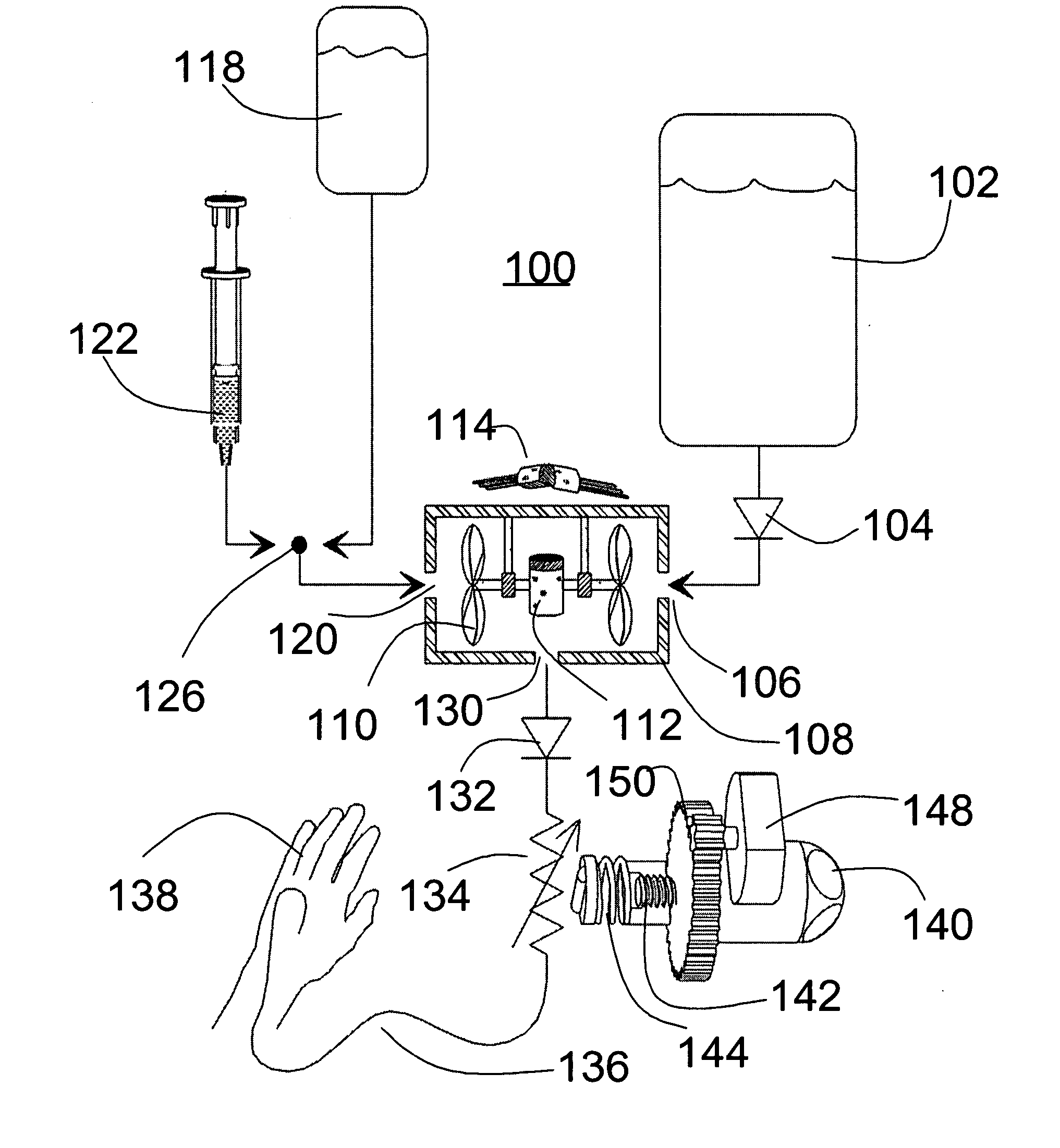
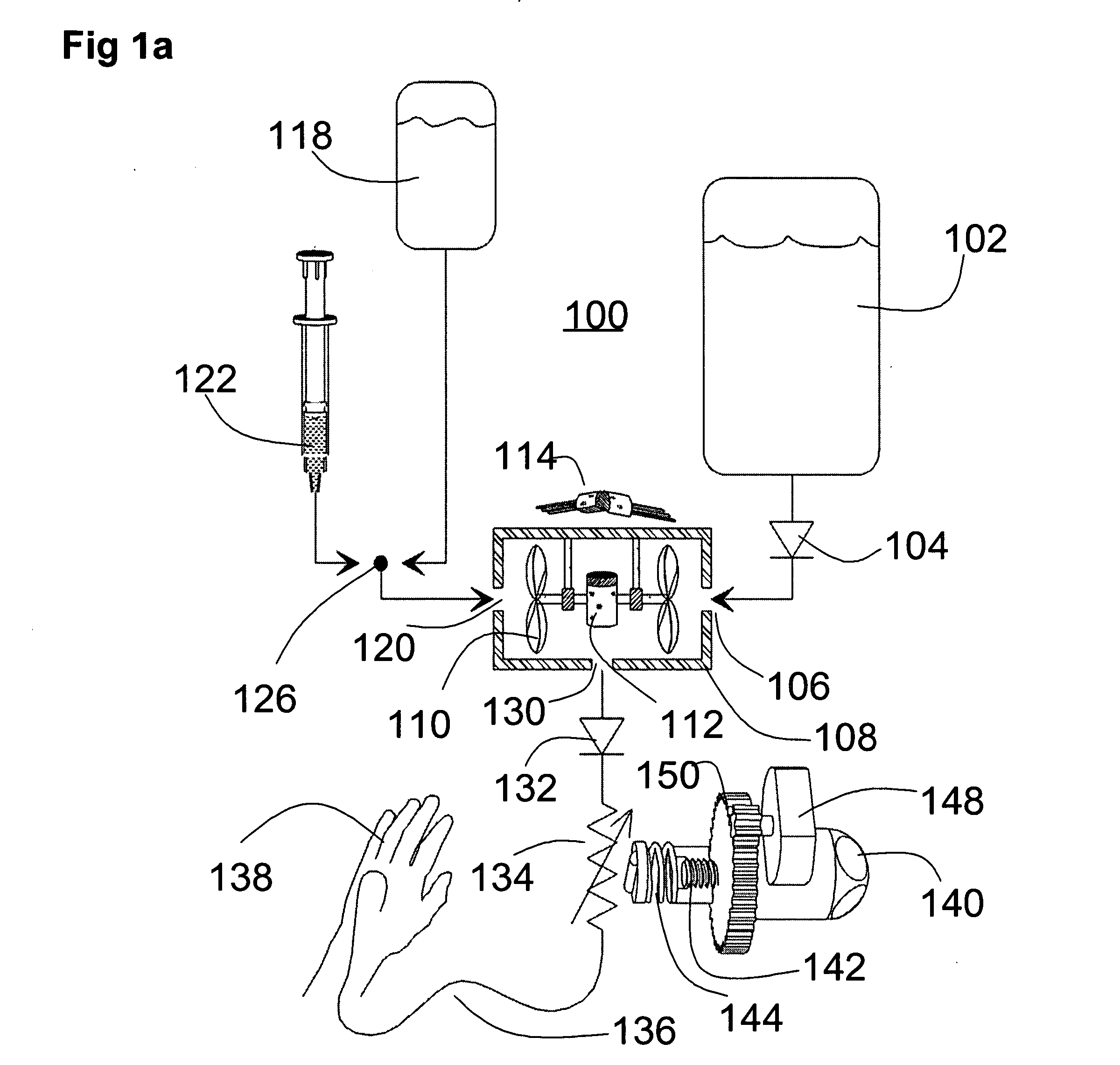
[0038] The essential components of the invention are described with reference to FIG. 1a. A medical fluid administration system 100 includes one or more sources of fluid, one or more one-way check valves, a bi-directional flow measurement device, and a variable fluid resistance, modulated manually, or by servomechanism, or both, all of which are described in detail herein.

[0039] Primary fluid source 102 is represented schematically as a large-volume bag. The content of primary fluid source 102 flows via primary check valve 104 and into primary input to impeller housing 106 of impeller housing 108. The movement of fluid causes impeller 110 to turn in a given direction based on the geometry of impeller 110. In one embodiment of the present invention, impeller 110 is connected to permanent magnet 112, causing permanent magnet 112 to turn as impeller 110 turns. Electromagnet coils 114 may be used as a sensor to detect movement of permanent magnet 112. It is contemplated that other embo...


PUM


Abstract

A device for control of fluid flow with closed loop quasi static adjustment of in-line pressure-based resistance. The disclosed device and methods of using the device provide for the ability to control a flow rate with a highly portable device; the ability for an operator to safely use the device with minimal training; the ability to automatically switch between a primary and secondary fluid; the ability to maintain a flow rate through a tubing set even when the control device is removed; and the ability to measure fluids introduced with a manual bolus injection.

Description

RELATED APPLICATIONS [0001] This application claims priority to U.S. Provisional Patent Application Ser. No. 60 / ______, filed on Feb. 20, 2004, which was converted from U.S. patent application Ser. No. 10 / 783,042 filed on Feb. 20, 2004 under 37 CFR 1.53(c)(2).FIELD OF THE INVENTION [0002] The present invention relates to intravenous infusion therapy. More specifically, the invention relates to a system, components of the system and methods associated with the system for organizing the fluid flow for applications which require an accommodation of a broad flow rate range, a wide range of input and output pressures, and a wide range of delivered fluid viscosities, such as those seen with Intravenous (IV) infusion therapy. BACKGROUND [0003] Conventionally, healthcare providers have had three technical options for the intravenous infusions. Many intravenous infusions are controlled by manually adjusting a resistance in the flow path between a fluid source and the patient, based on the op...

Claims


Application Information

Patent Timeline
IPC IPC(8): A61M5/00
CPCA61M5/1408A61M5/16877A61M5/16813A61M5/14236
Inventor CARLISLE, JEFFREY ALANKUBA, LAWRENCE MICHAEL
Owner FRESENIUS KABI USA LLC
Why Eureka
Try Eureka