Directional laser probe

a laser probe and directional technology, applied in the field of microsurgical laser probes, can solve the problems of inability to achieve optimal laser light delivery to the surgical site, inability to insert curved laser probes through straight cannulas, and difficult to use straight laser probes. to achieve the effect of easy deflection

Inactive Publication Date: 2006-01-05
SYNERGETICS
View PDF18 Cites 35 Cited by
  • Summary
  • Abstract
  • Description
  • Claims
  • Application Information

AI Technical Summary

Benefits of technology

[0009] The directional laser probe of the present invention may be constructed having either a disposable hand piece or a reusable hand piece and, although described as transmitting laser light, it may also be employed in transmitting light for illumination. The directional laser probe makes use of a shape memory metal alloy, nitinol, to steer and direct a flexible optic fiber to a surgical target site. Alternative shape memory materials such as spring steel or plastics may also be used. Whether the target site lies in the posterior or anterior portions of the eye interior, the directional laser probe can easily deflect to any angle between 0° (or a straight configuration) and 90° or more. The flexible nature of the shape memory material allows variable adjustment of the bend angle of the probe to deliver laser energy to the target site. Additionally, cannulas may be used in the incision site of the eye because the laser probe, when in its straight configuration, can be inserted through the cannula to position the tip of the probe in the interior of the eye, and then a bend can be created at the tip of the probe in the eye interior. The directional laser probe is especially useful when accessing anterior portions of the retina, or areas that are difficult or awkward to access using traditional straight probes.
[0014] In use of both embodiments the sleeve is then inserted through a cannula positioned in an incision in the eye or the sleeve is inserted directly through the incision, positioning the sleeve in the eye interior. In the first embodiment, the finger pad is then slowly moved toward the rear of the handle causing the sleeve to slowly move toward its pulled back position relative to the handle. In the second embodiment, the finger pad is moved slowly toward the front of the handle causing the optic fiber to slowly move toward its pushed forward position relative to the handle. In both embodiments the distal end portion of the optic fiber contained in the pre-bent portion of the tubular shape memory tip gradually bends from its straight configuration toward its 90° configuration. The bending of the fiber allows optimal positioning of the fiber tip to areas where a straight fiber may not reach. Rotation of the entire instrument about its center axis may be necessary to further direct the optic fiber tip. Once the proper location of the fiber tip is achieved, laser energy can then be delivered to the site of interest.

Problems solved by technology

Efficient delivery of laser light in the eye interior toward the anterior or front portion of the retina is often awkward to the surgeon using a straight laser probe.
However, curved laser probes cannot be inserted through straight cannulas and therefore must be directed through the eye incision site itself.
In this situation the optimal delivery of laser light to the surgical site cannot be achieved.
Additionally, torquing or manipulating the tubular sleeve of the straight probe in the entry incision to reduce the angle of approach of the laser light to the surgical site in these awkward areas often produces excessive, and sometimes harmful stresses around the incision of the eye.
However, because their curvatures are fixed, curved laser probes are not efficient at directing laser energy to areas even more anterior or more forward in the eye that would require a tighter bend or curvature of the probe sleeve, or areas at the far end or posterior of the retina which would require a straight sleeve laser probe due to the approach angle.

Method used


Image

  • Directional laser probe
  • Directional laser probe
  • Directional laser probe

Examples


first embodiment

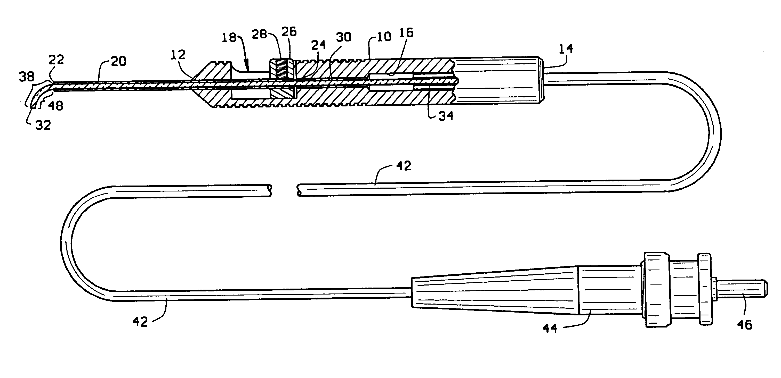
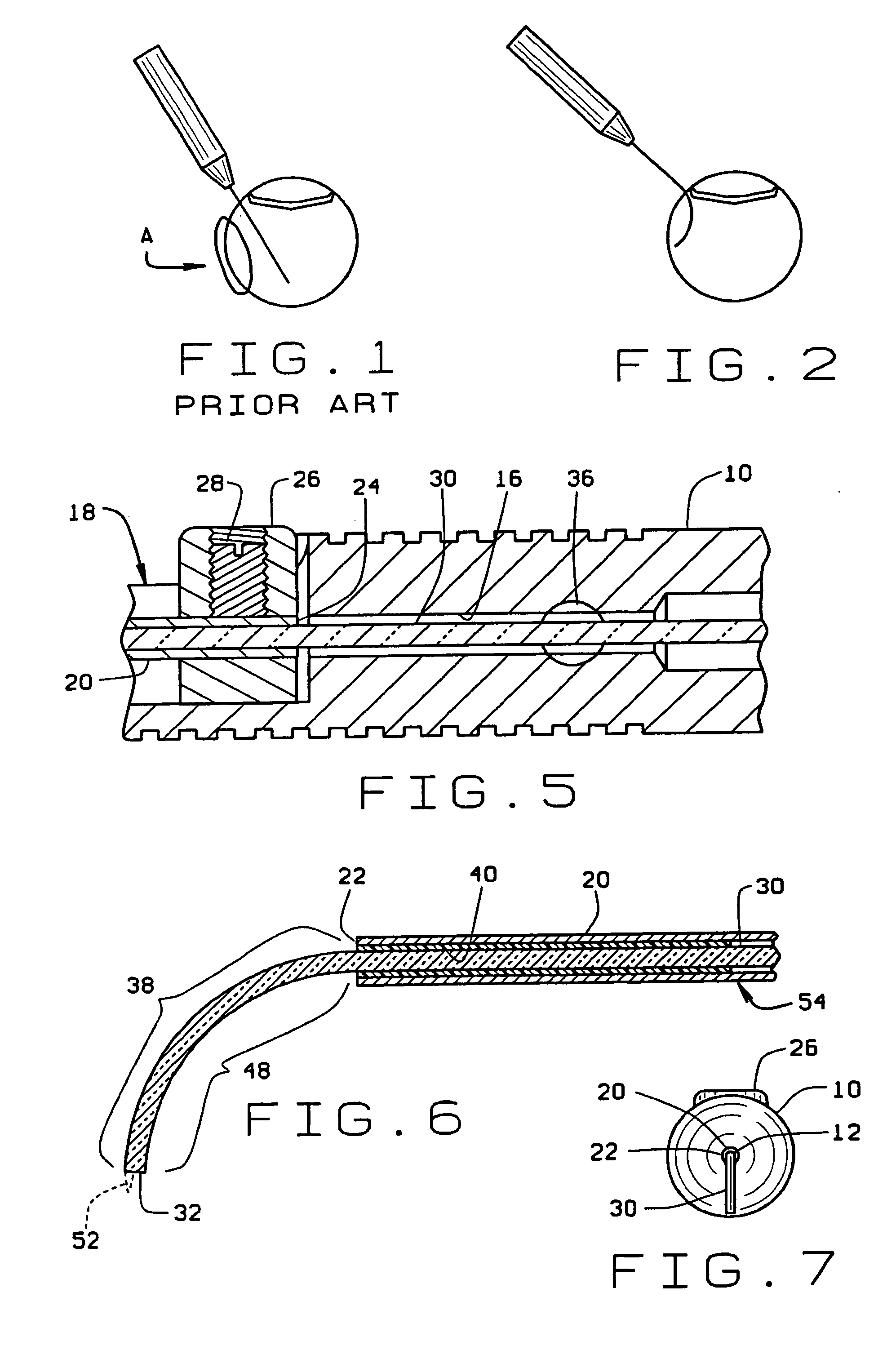
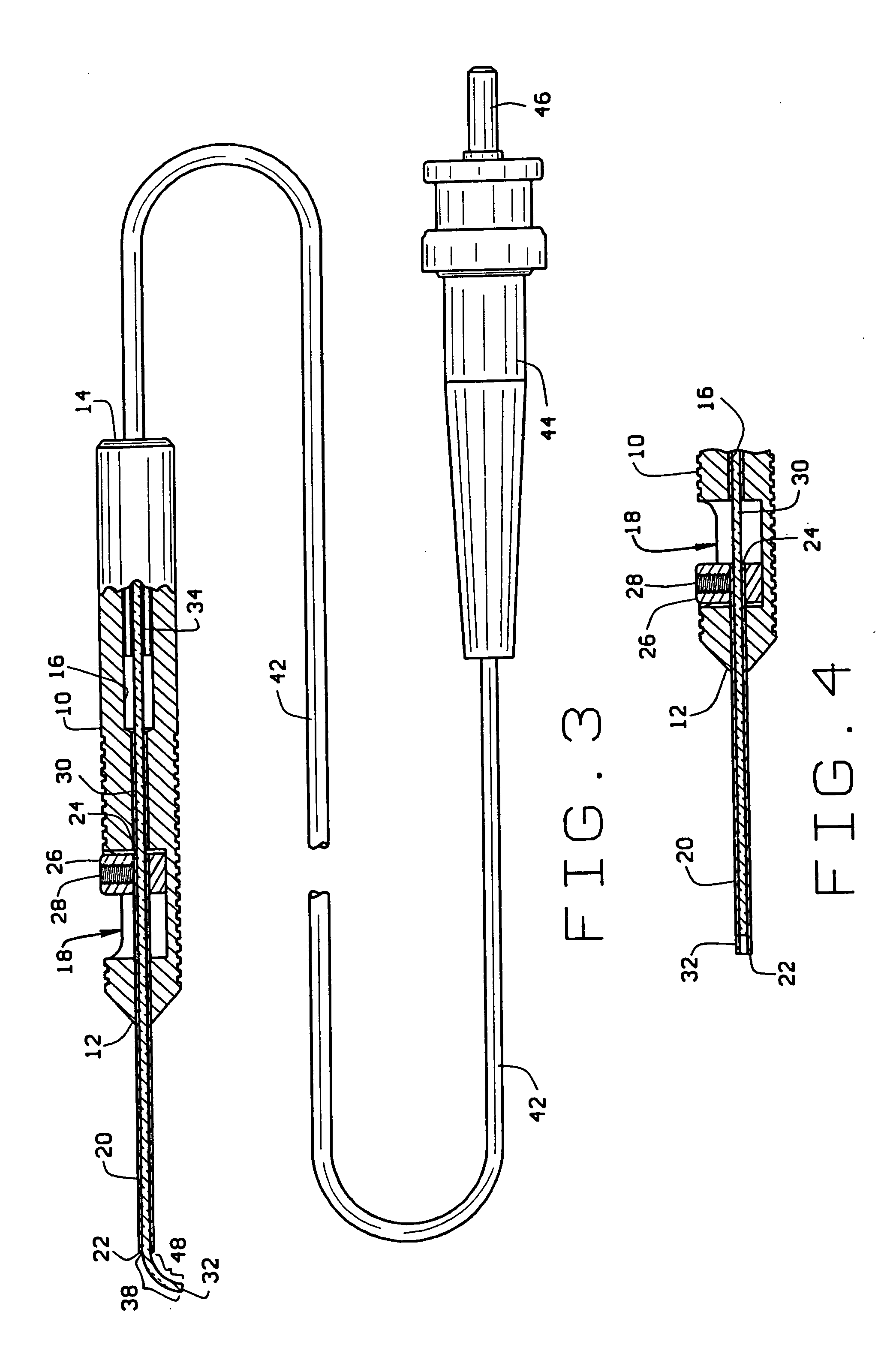
[0034] In use of the directional laser probe, the optic fiber connector 44 is first attached to a laser power source. With the finger pad 26 in its pushed forward position, the optic fiber is contained in the sleeve 20 which projects in a straight line from the distal end of the handle. The sleeve 20 is then inserted through a cannula positioned in an incision in the eye or inserted directly through the incision positioning the sleeve in the eye interior. The finger pad 26 is then slowly moved toward the rear of the handle causing the sleeve 20 to slowly move toward its pulled back position relative to the handle. This, in turn, causes the distal end portion 48 of the optic fiber contained in the pre-bent portion 38 of the shape memory tip to gradually bend from its straight configuration toward its 90° configuration. The bending of the fiber allows optimal positioning of the fiber tip to areas where a straight fiber may not reach. Rotation of the entire instrument about its center ...

second embodiment

[0038] the directional laser probe shown in FIGS. 8 and 9 has an elongate narrow handle or hand piece 10′ having opposite distal 12′ and proximal 14′ ends. The handle 10′ is dimensioned to a size similar to that of a pencil to fit comfortably in the surgeons hand. The handle is preferably manufactured of a disposable medical grade plastic. A hollow bore 16′ extends through the center of the handle from its distal end 12′ to its proximal end 14′. The handle center bore 16′ has a center axis that defines mutually perpendicular axial and radial directions relative to the handle 10′. The bore 16′ has a necked down portion adjacent the handle distal end 12′. A recess 18′ is formed radially into a side of the handle and intersects with the center bore 16′. The recess 18′ extends axially along a short length of the handle forming an axial slot in the side of the handle.

[0039] A cylindrical, narrow rigid tube or sleeve 20′ is received in the necked down portion of the handle bore 16′ at the...


PUM


Abstract

A microsurgical laser probe is provided with a distal end portion of an optic fiber that projects from a tubular sleeve of the probe and can be caused to bend relative to the probe sleeve by manual manipulation of a mechanism on a handle of the probe.

Description

[0001] This patent application is a divisional of patent application Ser. No. 10 / 409,874, which was filed on Apr. 9, 2003, and is currently pending, and is a continuation-in-part of patent application Ser. No. 09 / 545,143, which was filed on Apr. 7, 2000.BACKGROUND OF THE INVENTION [0002] (1) Field of the Invention [0003] The present invention pertains to a microsurgical laser probe used primarily in ophthalmic surgery. The probe has a handle and a tubular sleeve and a distal end portion of an optic fiber projecting from the sleeve can be caused to bend relative to the sleeve by manual manipulation of a mechanism on the probe handle. [0004] (2) Description of the Prior Art [0005] In ophthalmic surgery, various different types of instruments are available for use by the surgeon to transmit laser energy to a surgical site in the interior of the eye. The typical microsurgical laser probe comprises a handle with a small cylindrical metal sleeve projecting from a distal end of the handle....

Claims


Application Information

Patent Timeline
Patent Type & Authority Applications(United States)
IPC IPC(8): A61B18/22A61BA61B17/00A61B17/22A61B18/18A61F9/008
CPCA61B17/3207A61B18/22A61B18/24A61B2017/00867A61B2018/00196A61F2009/00863A61B2018/225A61B2018/2288A61B2019/5206A61F9/008A61B2018/2238A61B3/16A61B2090/306A61B90/30
Inventor SCHELLER, GREGG D.AULD, MICHAEL D.
Owner SYNERGETICS
Why Eureka
Try Eureka