
Low-bitrate encoding/decoding method and system

a low-bitrate, encoding/decoding technology, applied in the field of encoding/decoding methods and systems, can solve the problems of data storage and transmission, significant differences in efficiency between signals, and inability to achieve optimum quantization techniques, etc., to achieve low bitrate, effectively compress data, and low bitrate

Inactive Publication Date: 2006-01-05
SAMSUNG ELECTRONICS CO LTD
View PDF10 Cites 45 Cited by
  • Summary
  • Abstract
  • Description
  • Claims
  • Application Information

AI Technical Summary

Benefits of technology

[0013] The present invention provides a low bitrate audio encoding / decoding method and system that can effectively compress data at a relatively low bitrate and thus provide a high quality audio signal using algorithms for reducing and recovering frequency components.

Problems solved by technology

While this digital storing / restoring technology is much improved in terms of sound quality and storage as compared to an analog source, such as a long-play record (LP) or tape, there has been a problem in data storage and transmission due to a huge amount of digital data.
In order to overcome this problem, the differential pulse code modulation (DPCM) or adaptive differential pulse code modulation (ADPCM), which was developed to compress digital audio signals, has been employed to reduce the data size, but there has been a problem in that significant differences in efficiency occur depending on types of signals.
This quantization technique is simple but not optimum although input samples are statistically independent.
Of course, statistically dependent input samples are more problematic.
Accordingly, such an algorithm requires very complicated procedures as compared to an algorithm where only PCM data is encoded, and a bitstream includes additional information for compressing signals as well as quantized PCM data.

Method used


Image

  • Low-bitrate encoding/decoding method and system
  • Low-bitrate encoding/decoding method and system
  • Low-bitrate encoding/decoding method and system

Examples


Embodiment Construction

[0036] Reference will now be made in detail to the embodiments of the present invention, examples of which are illustrated in the accompanying drawings, wherein like reference numerals refer to the like elements throughout. The embodiments are described below to explain the present invention by referring to the figures.

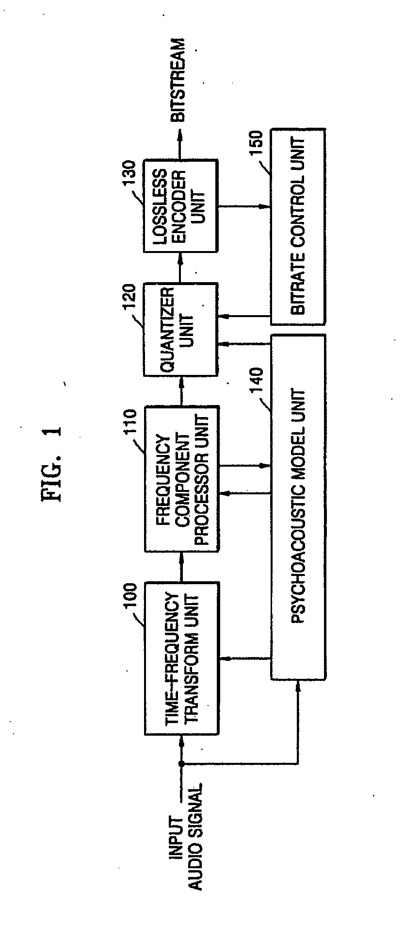
[0037]FIG. 1 is a block diagram showing an embodiment of a low bitrate audio encoding system according to an aspect of the present invention. The system comprises a time-frequency transform unit 100, a frequency component processor unit 110, a quantizer unit 120, a lossless encoder unit 130, a psychoacoustic model unit 140, and a bitrate control unit 150.

[0038] The time-frequency transform unit 100 transforms a time-domain audio signal into a frequency-domain audio signal. A modified discrete cosine transform (MDCT) may be used to transform a time-domain signal into a frequency-domain signal.

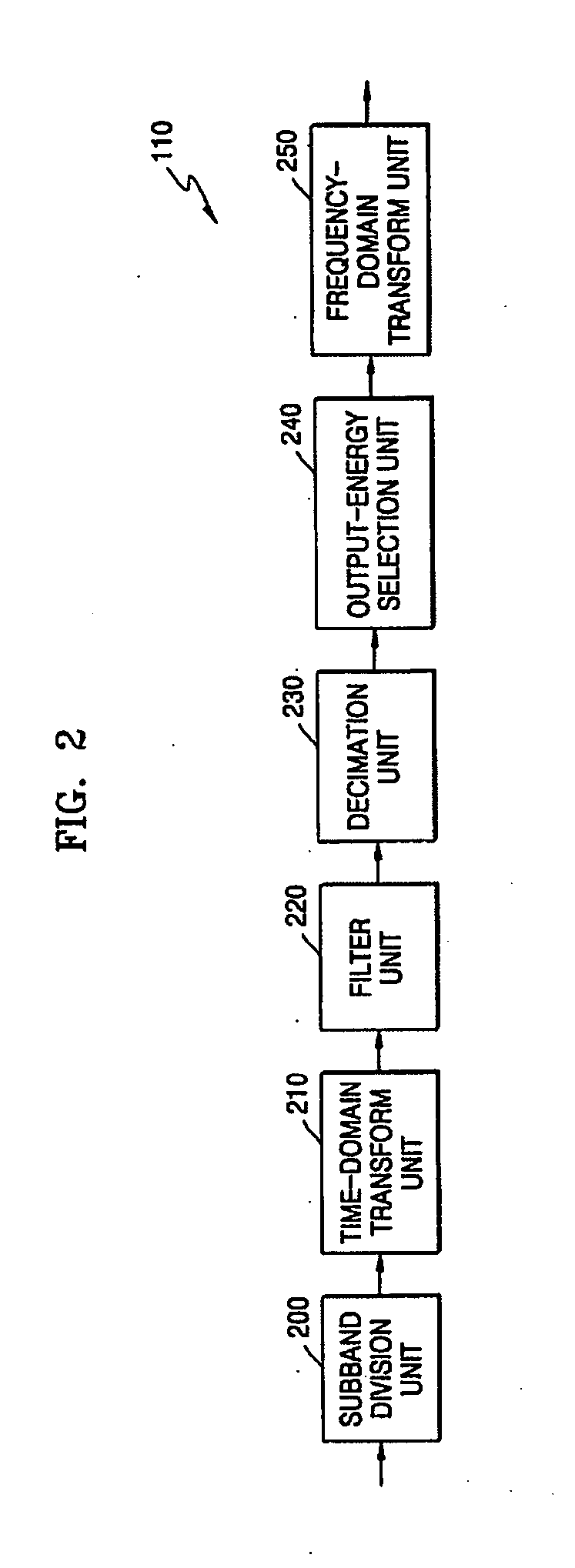
[0039] The frequency component processor unit 110 receives a frequency-dom...


PUM


Abstract

A low-bitrate encoding system includes: a time-frequency transform unit transforming an input time-domain audio signal into a frequency-domain audio signal; a frequency component processor unit decimating frequency components in the frequency-domain audio signal; a psychoacoustic model unit modeling the received time-domain audio signal on the basis of human auditory characteristics, and calculating encoding bit allocation information; a quantizer unit quantizing the frequency-domain audio signal input from the frequency component processor unit to have a bitrate based on the encoding bit allocation information input from the psychoacoustic model unit; and a lossless encoder unit encoding the quantized audio signal losslessly, and outputting the encoded audio signal in a bitstream format. Using the low-bitrate encoding system, it is possible to effectively compress data at a low bitrate, and thus to provide a high quality audio signal.

Description

CROSS-REFERENCE TO RELATED APPLICATION [0001] This application claims the benefit of Korean Patent Application No. 2004-48036, filed on Jun. 25, 2004, in the Korean Intellectual Property Office, the disclosure of which is incorporated herein in its entirety by reference. BACKGROUND OF THE INVENTION [0002] 1. Field of the Invention [0003] The present invention relates to an encoding / decoding method and system, and more particularly, to a low bitrate encoding / decoding method and system that can efficiently compress data at a low bitrate and thus provide a high quality audio signal. [0004] 2. Description of the Related Art [0005] A waveform including information is originally an analog signal which is continuous in amplitude and time. Accordingly, analog-to-digital (A / D) conversion is required to represent a discrete waveform. A / D conversion comprises two distinct processes: sampling and quantizing. Sampling refers to the process of changing a signal continuous in time into a discrete ...

Claims


Application Information

Patent Timeline
Patent Type & Authority Applications(United States)
IPC IPC(8): G10L21/00H03M7/30G10L19/02
CPCG10L19/0017G10L19/032G10L19/0204H03M7/30
Inventor OH, EUNMIKIM, JUNGHOEKIM, SANGWOOKEGOROV, ANDREWPOROV, ANTONOSIPOV, KONSTANTINKUDRYASHOV, BORIS
Owner SAMSUNG ELECTRONICS CO LTD
Learn More