This helps you quickly interpret patents by identifying the three key elements:
Problems solved by technology
Method used
Benefits of technology
Benefits of technology
[0010] Accordingly, it is an object of the present invention to provide a cooling structure for electronic equipment that is capable of efficiently cooling the heat-generating body and inhibiting the adverse effect produced on the case by the increase in temperature of the heat-dissipating section employed for dissipating the heat recovered from the heat-generating body.
[0012] With such a configuration, because the heat-dissipating section is provided inside the thermally insulated space, even when the quantity of heat generated by the heat-generating body is increased and the heat-dissipating section is heated to a higher temperature, the risk of heating the electronic components located in the vicinity of the heat-dissipating section or the case itself is eliminated. Therefore, even if the quantity of heat generated by the heat-generating body increases, it is possible to avoid the risk of thermally damaging the electronic components located in the vicinity of the heat-dissipating section. At the same time, the outer wall temperature of the case is comparatively easily held within the ergonomically preferred temperature range (for example, below 40° C.).
[0017] It is preferred that a heat-absorbing surface of a Peltier element be connected to the heat-dissipating section, and a heat-generating surface of the Peltier element be exposed to the thermally insulated space. With such a configuration, cooling of the heat-dissipating section connected to the heat-absorbing surface is efficiently conducted with a heat pump function of the Peltier element and cooling of the heat-generating body can be conducted more efficiently. Furthermore, because the temperature of the heat-generating surface becomes higher than that of the heat-dissipating section, the difference in temperature between the heat-generating surface and the air becomes larger than the difference in temperature between the heat-dissipating section and the air and the heat transfer rate of the air further increases. In other words, the Peltier element demonstrates the effect of enhancing the forcible cooling of the heat-dissipating body with the fan and further enhancing the cooling function.
[0018] The cooling structure preferably further comprises monitoring means for monitoring the temperature of the heat-generating body, judgment means for judging as to whether or not the temperature of the heat-generating body monitored by the monitoring means has reached a prescribed temperature, and control means for controlling the drive power of the Peltier element, a pump contained in the heat transfer means, and the fan according to the judgment results obtained with the judgment means. With such a configuration, the drive of the Peltier element can be conducted as necessary only in the case where the amount of heat generated by the heat-generating body increases and the forcible cooling of the heat-dissipating section with the fan alone becomes insufficient. For this reason, power consumption can be reduced and the amount of heat generated in the Peltier element when the Peltier element is driven can be also reduced.
Problems solved by technology
As a result, there is a risk of temperature increasing in the electronic equipment and, for example, the CPU exploding or fracturing under the effect of heat.
However, with such a technology, because spontaneous cooling (spontaneous heat dissipation) is used for heat dissipation, only a limited cooling efficiency can be attained.
Furthermore, because the size of the case has to be increased to increase the heat dissipation quantity, the requirements relating to miniaturization and thickness reduction of equipment cannot be fully met.
Moreover, because heat dissipation from the case is used, the increase in the temperature of the case cannot be avoided and the user feels uncomfortable when touching the case.
However, though the cooling technology of Japanese Patent Application Laid-open No. 2002-163041 provides for forced cooling with a fan, no special thermal insulation treatment is carried out with respect to the display section case.
Therefore, heat is unavoidably transferred to the display section case in an amount equivalent to that during heat dissipation.
Therefore, the temperature of the display section case rises and the user feels uncomfortable when touching the case.
Method used
Image
Click on the blue label to locate the original text in one second.
Reading with bidirectional positioning of images and text.
Examples
first embodiment
[0056] The cooling structure for a notebook PC of the present invention will be described in detail hereinbelow with reference to FIGS. 1 to 5.
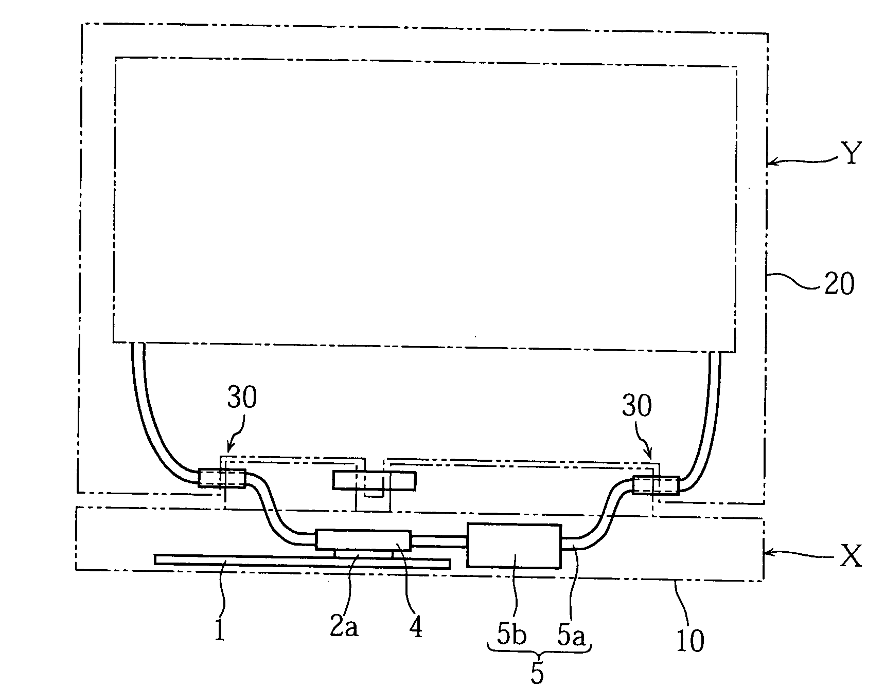
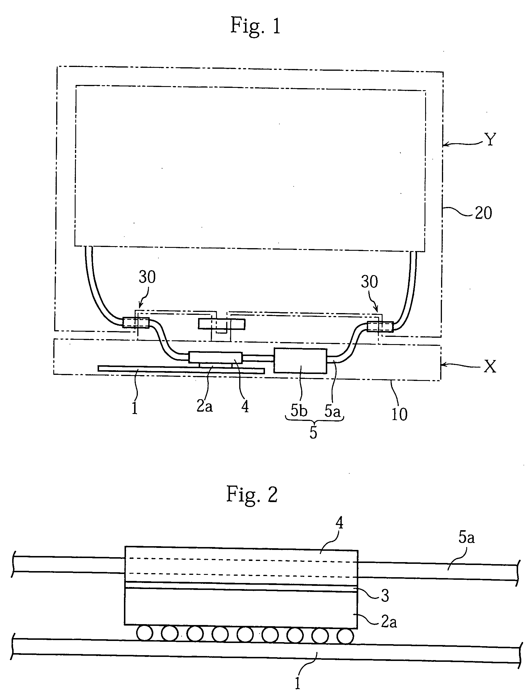
[0057]FIG. 1 is a schematic front view of a notebook PC composed of a main body section X and a display section Y rotatably linked to the main body section X. In FIG. 1, the outer contour of a case 10 of the main body section X and the outer contour of a case 20 of the display section Y are shown by two-dot-dash lines. FIG. 2 is an enlarged view of the main portion of the structure shown in FIG. 1.
[0058] A circuit substrate 1 supported inside the case 10 is disposed in the main body section X. Electric and electronic elements, integrated circuits, and electronic circuit groups necessary for operating the notebook PC are mounted on the circuit substrate 1. Furthermore, a CPU, a MPU, and a chip set that become heat-generating sources during operation of the notebook PC are also disposed thereon. The main body section X also accommodates other ...
second embodiment
[0084] The cooling structure of the notebook PC of the present invention will be described below in greater detail with reference to FIGS. 16 to 19. In those figures, members or elements identical or analogous to those of the above-described cooling structure are assigned with the same reference numerals and redundant explanation thereof is omitted.
[0085]FIG. 16 and FIG. 17 show a notebook PC composed of a main body section X, a display section Y rotatably linked to the main body section X, and a heat-dissipating section Z. FIG. 16 is a front view thereof and FIG. 17 is a side view thereof. FIG. 18 is a cross-sectional view along the line XVIII-XVIII shown in FIG. 17. In FIG. 16, the outer contour of a case 10 of the main body section X and the outer contour of a case 20 of the display section Y are shown by two-dot-dash lines.
[0086] The main body section X, as shown in FIG. 16, comprises a circuit substrate 1 and a heat-generating body 2a inside the case 10. In the second embodime...
third embodiment
[0095] The cooling structure of the space-saving PC of the present invention will be described below in greater detail with reference to FIGS. 22 to 29. In those figures, members or elements identical or analogous to those of the above-described cooling structure are assigned with the same reference numerals and redundant explanation thereof is omitted.
[0096] FIGS. 22 to 25 are schematic views of he space-saving PC composed of the main body section X′ also serving as a display section and the heat-dissipating section Z rotatably linked to the main body section X′ also serving as a display section. FIG. 22 is a front view thereof, FIG. 23 is a right side view thereof, FIG. 24 is a left side view thereof, and FIG. 25 is a rear view thereof. Further, FIGS. 26 and 27 are the enlarged schematic views of the heat-dissipating section Z, FIG. 26 is the front view thereof, and FIG. 27 is a rear view thereof. FIG. 28 is a cross-sectional view along the line XXVIII-XXVIII shown in FIG. 26 and ...
PUM
Abstract
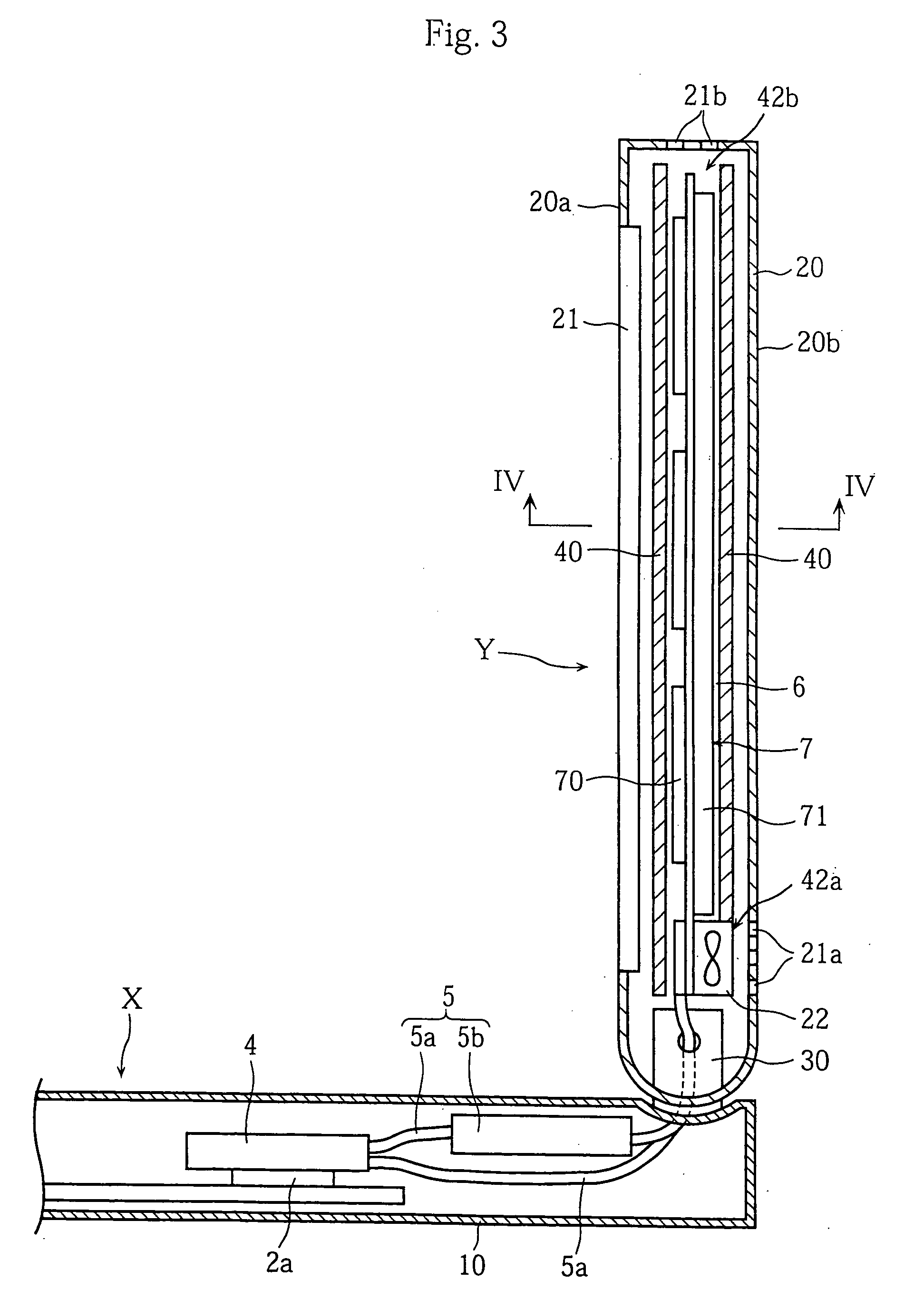
A cooling structure for electronic equipment is designed for cooling a heat-generating body (2a) disposed inside a case (20) by recovering heat generated by the heat-generating body (2a) and dissipating the heat to the outside of the case (20). The cooling structure includes a heat-receiving section (4) for recovering heat generated in the heat-generating body (2a), a thermally insulated space (6) provided with an air inflow orifice (42a) and an air outflow orifice (42b) and thermally insulated from the heat-generating body (2a) and heat-receiving section (4) by a thermally insulating member (40), a heat-dissipating section (7) provided inside the thermally insulated space (6), a heat transfer member (5) for transferring the heat recovered in the heat-receiving section (4) to the heat-dissipating section (7), and a fan (22) for generating forcibly an air flow in the thermally insulated space (6). The heat generated by the heat-generating body (2a) is transferred to the heat-dissipating section (7) via the heat-receiving section (4) and heat transfer member (5) and dissipated in a concentrated fashion by using the fan (22) inside the thermally insulated space (6).
Description
TECHNICAL FIELD [0001] The present invention relates to a cooling structure for electronic equipment, and more particularly to a cooling structure for space-saving electronic equipment such as notebook personal computers. BACKGROUND ART [0002] In recent years a remarkable progress has been attained in performance improvement of electronic equipment. In particular, functional capabilities and speed of CPU or chip sets (referred to hereinbelow as “heat-generating body”) which are heat generation sources located inside the electronic equipment have been continuously increasing. On the other hand, miniaturization and thickness reduction of electronic equipment, in particular, space-saving electronic equipment such as notebook personal computers (referred to hereinbelow as “notebook PC”) are also strongly required. With this in view, rapid increase in heat generation per unit volume in electronic equipment can be anticipated. As a result, there is a risk of temperature increasing in the ...
Claims
Application Information
Patent Timeline
Application Date:The date an application was filed.
Publication Date:The date a patent or application was officially published.
First Publication Date:The earliest publication date of a patent with the same application number.
Issue Date:Publication date of the patent grant document.
PCT Entry Date:The Entry date of PCT National Phase.
Estimated Expiry Date:The statutory expiry date of a patent right according to the Patent Law, and it is the longest term of protection that the patent right can achieve without the termination of the patent right due to other reasons(Term extension factor has been taken into account ).
Invalid Date:Actual expiry date is based on effective date or publication date of legal transaction data of invalid patent.

