
Electromagnetic moving toy system

a technology of moving vehicles and toy systems, applied in the direction of toys, amusements, roundabouts, etc., can solve the problems of increased resistance of moving vehicles, difficulty in providing reliable speedy moving vehicles, and vehicle moving at high speed can lose stability and get off the track, so as to improve safety, simplify the system, and the effect of improving stability

Inactive Publication Date: 2006-01-12
INDAL DESIGN LAB
View PDF8 Cites 19 Cited by
  • Summary
  • Abstract
  • Description
  • Claims
  • Application Information

AI Technical Summary

Benefits of technology

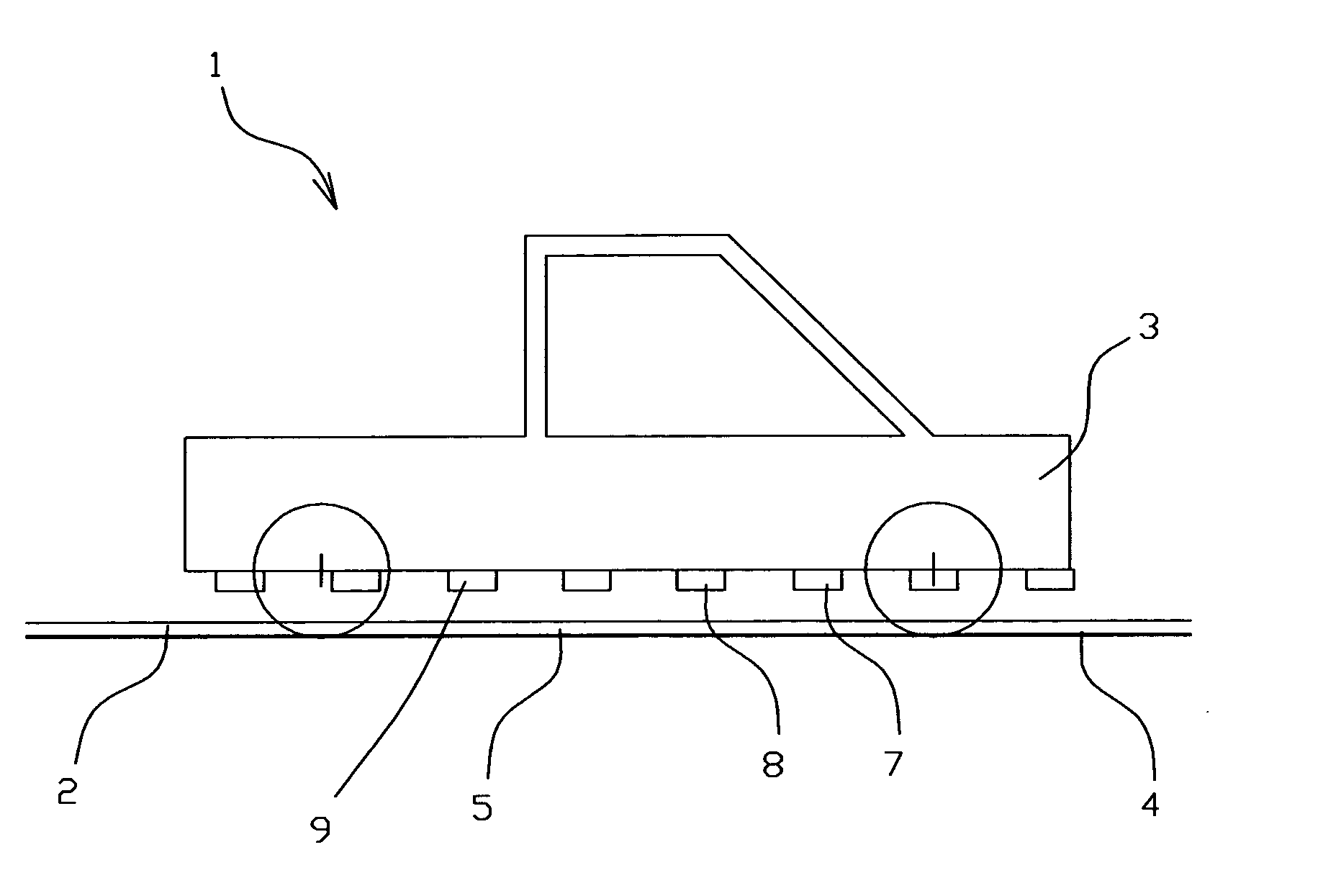
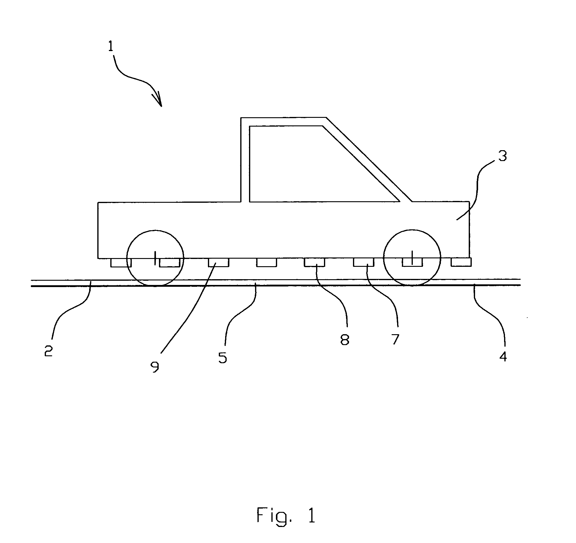
[0010] In order to achieve these objectives, according to the first embodiment of the present invention, the track comprises electrically connected coils windings, powered by electrical grid and controlled by switching controller in such way that at least two adjacent coil windings operating in time. The coils windings serve as a stator and located in a series way along the track. The vehicle comprises magnetic means interacting with the coils windings so the magnetic means serve as a moving body providing a possibility for moving of the vehicle.
[0012] The electromagnetic interaction between the coils windings of the track and the magnetic means of the vehicle not only moves the vehicle, but it also provides at the same time, reliable attraction between the vehicle and the track in any possible configuration and location without any special additional means for it. It makes the electromagnetic moving toy system much more stable, reliable and gives the opportunity to operate at higher speed of the vehicle and in any position of it, thus providing the possibility to make the track as vertical ring or spiral, or in any other configuration. It also simplifies the system and makes it more durable because it is not necessary to use any kind of brushes.
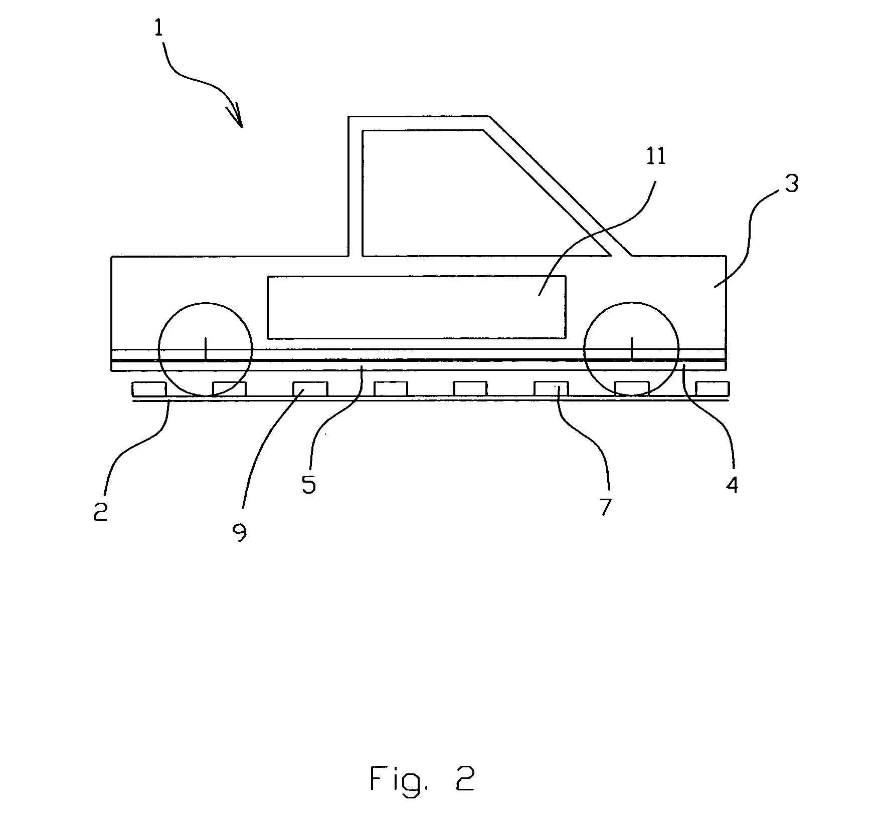
[0013] According to the second embodiment, the electrically connected coils windings placed on the bottom part of the vehicle and connected directly to a power source located on the vehicle. Magnetic means located in a series way along the track and interact with the coils windings located on the vehicle, thus represent another way to achieve the similar goal by using the same general idea. Magnetic means are made as permanent magnets located along the track with alternative polarity. It gives, in general, similar effect as mentioned first embodiment. Such configuration provides the minimum necessary power usage and, as a result, the essential economy of energy.
[0014] The coils windings serve as a stator. The stator may comprise a core made of magnet-conducting material with high eddy current resistance, made for example from silicon steel. In this case the efficiency of electromagnetic interaction between the coils windings of the vehicle and the magnetic means of the track is much higher that provides economy of energy.

Problems solved by technology

The main problem of all known systems is that it is very difficult to provide reliable speedy moving vehicle because of the lack of stable attraction between a vehicle and a track, especially at the higher speed on the turns, also with vertical or almost vertical sections as a vertical ring or spiral.
Even when track sections are located horizontally the vehicle moving with high speed can lose stability and get of the track.
But these means in known systems also make additional resistance to the moving vehicle and needs much more power to move it.
Or they might be batteries operating that not require any brushes, but instead need the control trough the wire or wireless and have limited operating time due to the batteries life.

Method used


Image

  • Electromagnetic moving toy system
  • Electromagnetic moving toy system
  • Electromagnetic moving toy system

Examples


Embodiment Construction

[0025] The present invention will be described in detail below with reference to the accompanying drawings.

[0026]FIGS. 1-6 show embodiments of the present invention.

[0027] The electromagnetic moving toy system 1 according to the preferred embodiment (FIGS. 1, 3, 4, 5 and 6) comprises a track 2 and a vehicle 3 moved on the track 2. The track 2 comprises electrically connected coils windings 4 serving as a linear stator 5 and located in a series way along the track 2. The coils windings 4 are powered in such way that at least two adjacent coil windings 6 and 6a (FIG. 6) operate in time. The vehicle 3 comprises magnetic means 7 interact with coils windings 4 so the magnetic means 7 serve as a moving body 8 provide a possibility for moving of the vehicle 3. The magnetic means 7 are made as permanent magnets 9 located along the vehicle 3 (FIGS. 1 and 4) with alternative polarity. The linear stator 5 may further comprise a core 10 made of magnet-conducting material with high eddy curren...


PUM


Abstract

An electromagnetic moving toy system comprises a track and at least one vehicle located on the track. The track comprises electrically connected coils windings serving as a linear stator and located in a series way along the track. The coils windings are powered in such way that at least two adjacent coil windings operating in time. The linear stator further comprises a core made of magnet-conducting material with high eddy current resistance. The vehicle comprising magnetic means interacting with the coils windings so the magnetic means serving as a moving body providing a possibility for moving of the vehicle. The magnetic means are made as permanent magnets with alternative polarity. According to another embodiment, the track comprises magnetic means located in a series way along the track. The vehicle comprises electrically connected coils windings serving as a linear stator powered by at least one autonomous power source.

Description

CROSS REFERENCE TO RELATED APPLICATIONS [0001] The present application claims the benefit of priority of U.S. Provisional Patent Application No. 60 / 586,122, filed Jul. 7, 2004 for Edward Lopatinsky at al. the entire content of which is incorporated herein by reference.FIELD OF THE INVENTION [0002] The present invention relates generally to electromagnetic moving systems. More particularly, the present invention relates to toy moving devices like cars on railways, amphibian vehicles and / or submarines. BACKGROUND OF THE INVENTION [0003] There are numerous designs of electromagnetic moving systems like miniature toy railway systems that include a track and at least one vehicle located on said track. [0004] There are known systems of this type, for example, U.S. Pat. No. 4,861,306 “Toy Cog Railway” and U.S. Pat. No. 6,648,724 “Toy Railway Liquid Transfer Facility”, that include the track (platform, chassis) driven by an engine and vehicle mounted on said track. [0005] Another type of th...

Claims


Application Information

Patent Timeline
Patent Type & Authority Applications(United States)
IPC IPC(8): A63G1/00
CPCA63H18/10A63H2018/165A63H18/16A63H18/14
Inventor LOPATINSKY, EDWARDFEDOSEYEV, LEVSCHAEFER, DANIEL
Owner INDAL DESIGN LAB
Learn More