Fuel injection system

a fuel injection and system technology, applied in the direction of fuel injecting pumps, electric control, machines/engines, etc., can solve the problems of deviation in actual injection timing, imposing a very heavy operational load on the controller, and affecting the operation of the controller

Active Publication Date: 2006-01-12
DENSO CORP
View PDF15 Cites 20 Cited by
  • Summary
  • Abstract
  • Description
  • Claims
  • Application Information

AI Technical Summary

Benefits of technology

[0012] The present invention was developed in view of the aforementioned problems. It is therefore the object of the present invention to provide a fuel injection system that allows for the reduction of the adaptation steps to correct the output duration and timing of a drive pulse for drivingly closing or opening an injector.
[0013] The fuel injection system employing the means according to a first aspect determines a geometry defined by a change in injection rate of the injector with respect to time, and drive signal generation timing and drive signal termination timing of the injector from the geometry of the injection rate having an area corresponding to the request injection quantity Q. As described above, the fuel injection system employing the means according to the first aspect determines the drive signal generation timing and the drive signal termination timing of the injector from the geometry of the injection rate having an area corresponding to the request injection quantity Q. Accordingly, this permits an operational result (the formation of the geometry of the injection rate) based on a certain factor (e.g., a change in valve opening pressure achieving time Tds) to be automatically reflected on another operational result (such as the drive signal generation timing or the drive signal termination timing that is derived from the geometry of the injection rate). It is thus possible to significantly reduce the adaptation time required of the controller. The fuel injection system employing the means according to a second aspect determines the geometry defined by a change in needle lift quantity of the injector with respect to time and converts the geometry of needle lift quantity to determine the geometry of the injection rate.
[0015] The fuel injection systememploying the means according to a fourth aspect allows the geometry of the injection rate to be drawn at least using a pressure at which high-pressure fuel is supplied to the injector and a specification of a discharge line of the injector. That is, using the supply fuel pressure and the specification of the discharge line of the injector makes it possible to draw the geometry of the injection rate at which fuel is injected from the injector.
[0021] The fuel injection system employing the means according to a ninth aspect determines the valve opening pressure achieving time Tds by the function of a pressure of the high-pressure fuel supplied to the injector and multiple-injection intervals at which fuel is injected separately a multiple number of times in one cycle. The fuel injection system employing the means according to a tenth aspect employs, when correcting for a variation in injection quantity, at least one of the injection parameters (Tds, Qup, Qdn, Qmax, Tdel, Tqr, and Tqf) as an adjustment parameter and stores the adjustment parameter as a learned value to reflect the value on the next injection. This arrangement allows for correction of a variation in injection quantity corresponding to the difference between individual fuel injection systems and the degradation therein.
[0023] The fuel injection system employing the means according to a twelfth aspect estimates, when correcting for a variation in injection quantity, the variation in injection quantity as being caused by a change in a parameter of a predetermined portion defining a specification of the injector to employ the parameter of the predetermined portion as an adjustment parameter and store the adjustment parameter as a learned value to reflect the value on the next injection. The parameter of a predetermined portion defining the specification of the injector is corrected in this manner, thereby allowing for correction of the injection parameter determined using the parameter of the predetermined portion. That is, the geometry of a corrected injection rate is drawn, thus requiring no additional correction (such as injection quantity or injection timing).

Problems solved by technology

As shown in FIG. 5, in a multiple number of times of injection in one cycle, the second and subsequent stage injections are affected by the previous injection (due to pulsation that occurs in a line for supplying fuel to the injector), which leads to a variation in injection commencement delay or injection termination delay.
This causes a deviation in actual injection timing before or after the request injection start timing made by the controller.
Accordingly, for example, in multi-stage injection, it is necessary to perform an operational step using a number of independent correction maps by the number of the injection stages, thereby imposing a very heavy operational load on a controller.
This load is caused by the multiple operation steps of correcting the drive pulse and thus an enormous number of adaptation steps are required for the operational step.

Method used


Image

  • Fuel injection system
  • Fuel injection system
  • Fuel injection system

Examples


first embodiment

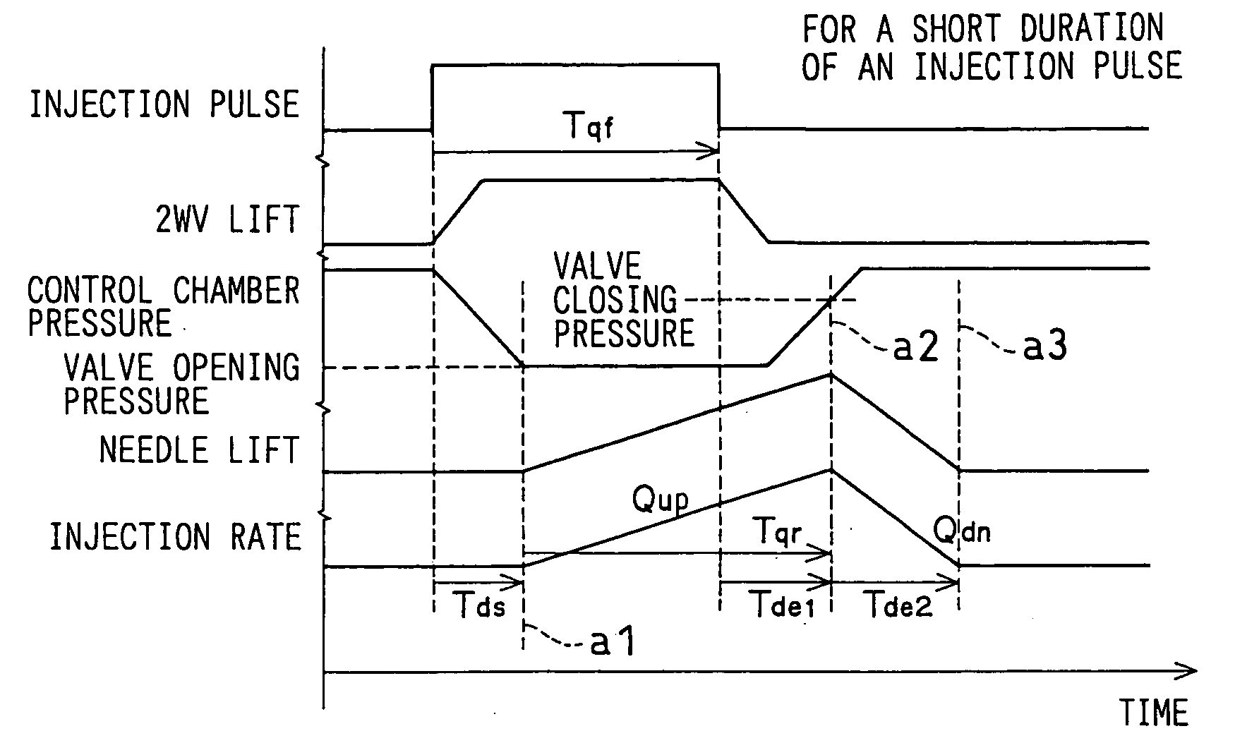
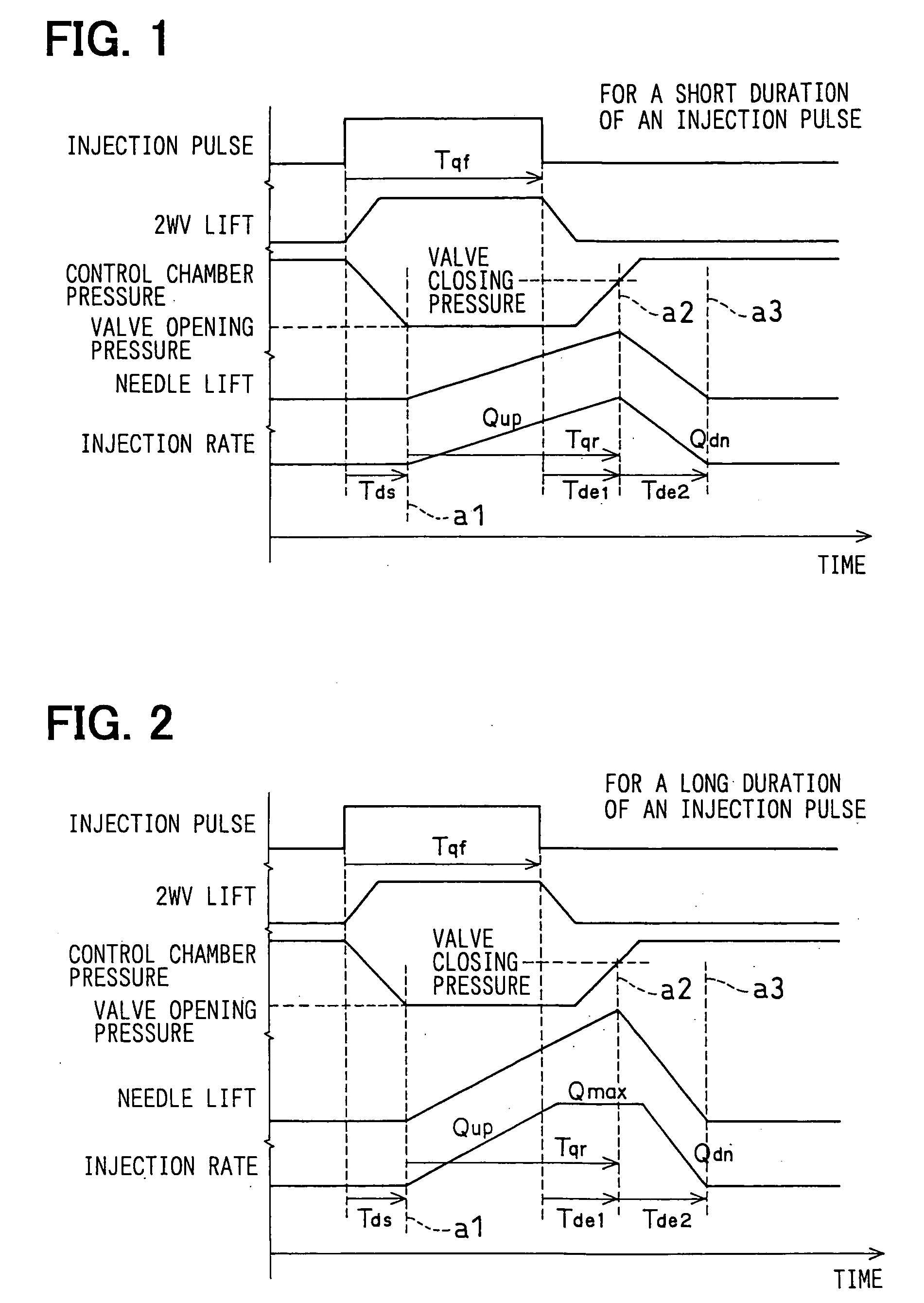
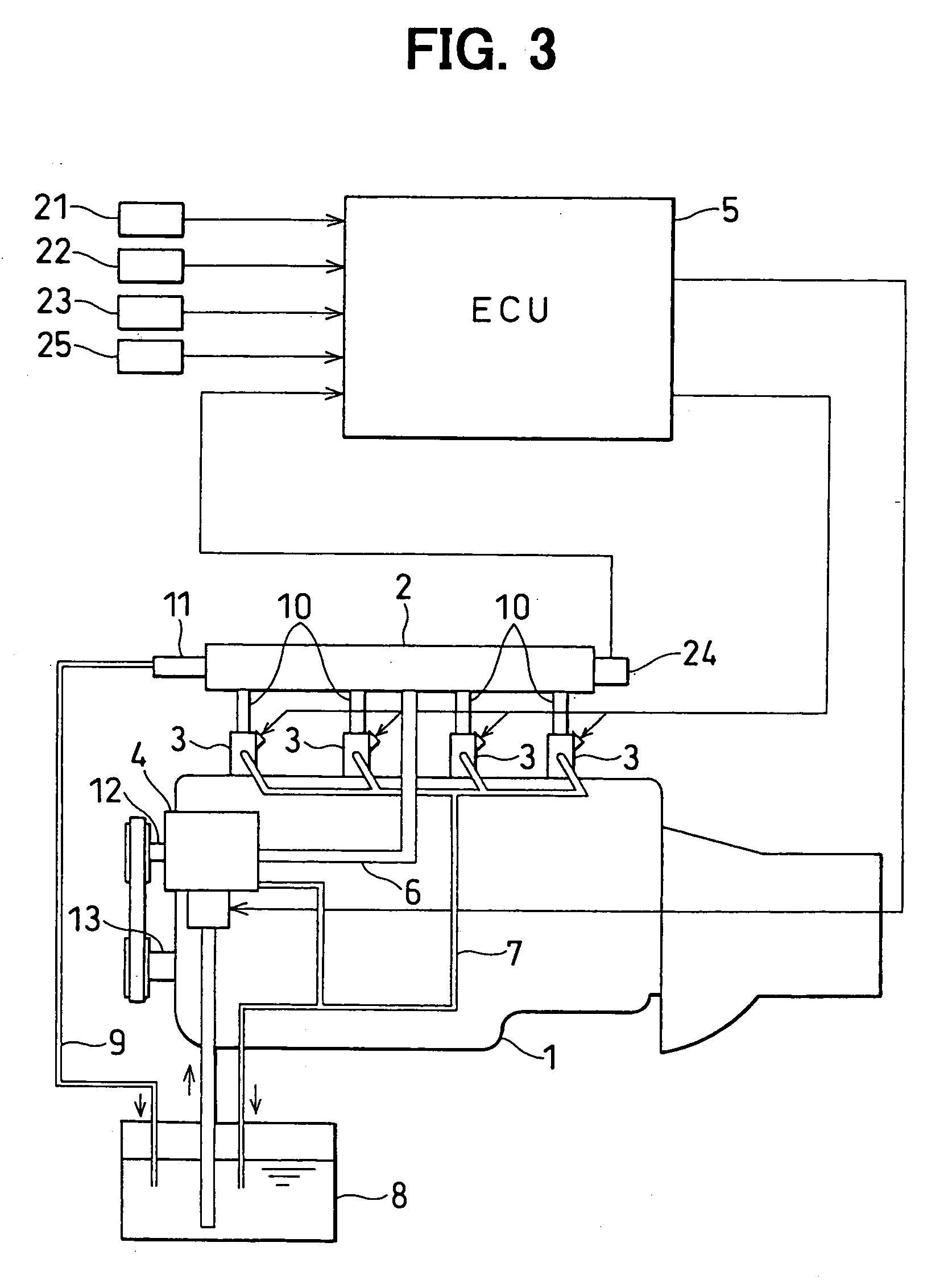
[0035] Now, reference is made to FIGS. 1 to 4 to explain the first embodiment of the present invention, which is applied to a common rail fuel injection system. First, the configuration of the common rail fuel injection system will be explained with reference to FIG. 3. As an example, the common rail fuel injection system is designed to inject fuel into a diesel engine (hereinafter referred to as an engine) 1, and includes a common rail 2, injectors 3, a supply pump 4, and an ECU 5 (abbreviated as Engine Control Unit, corresponding to a controller). The engine 1 has a multiple number of cylinders, each of which experiences an intake, compression, combustion, and exhaust stroke. As an example, FIG. 3 shows a four-cylinder engine, however, the present invention is also applicable to an engine having a different number of cylinders.

[0036] The common rail 2 is an accumulator vessel for accumulating high-pressure fuel to be supplied to the injector 3. The common rail 2 is connected to t...

second embodiment

[0076] In the first embodiment above, such an example was shown in which the rising injection rate Qup, the falling injection rate Qdn, and the maximum injection rate Qmax were directly determined, which were then used to determine the geometry of the injection rate. The example was also adapted such that the rising injection rate Qup, the falling injection rate Qdn, and the maximum injection rate Qmax were determined using the function or map based on the injector supply pressure (the common rail pressure Pc) and the specification of the injector 3. That is, in the first embodiment above, such an example was shown in which the geometry of the injection rate was directly determined using the function or map based on the injector supply pressure (the common rail pressure Pc) and the specification of the injector 3.

[0077] In contrast to this, in the second embodiment, a geometry defined by a change in needle lift quantity with respect to time is first determined, and then the geometr...

fourth embodiment

[0083] For the correction function according to the third embodiment above, such an example was shown in which correction was made using, as an adjustment parameter, at least one of the injection parameters consisting of the valve opening pressure achieving time Tds, the rising injection rate Qup, the falling injection rate Qdn, the maximum injection rate Qmax, the valve closing pressure achieving time Tde1, the needle rise time Tqr, and the injection pulse duration Tqf. In contrast to this, to correct for a variation in injection quantity, the correction function according to the fourth embodiment employs two or more of the injection parameters as adjustment parameters, while weighting the adjustment parameters for the correction of the variation in injection quantity and storing the respective adjustment parameters as a learned value to reflect the value on the next injection.

[0084] As a specific example, suppose that when a variation in revolutions per minute of the engine is de...


PUM


Abstract

During a short duration injection, a triangular geometry is drawn in terms of the injection rate with respect to time, while a trapezoidal geometry is drawn during a long duration injection. The ON timing of the drive pulse is determined to be at a valve opening pressure achieving time before the start point of formation in time of the geometry. An injection pulse duration is determined from “the valve opening pressure achieving time+a needle rise time—a valve closing pressure achieving time,” and then the OFF timing of the drive pulse is determined.

Description

CROSS REFERENCE TO RELATED APPLICATIONS [0001] This application is based upon, claims the benefit of priority of, and incorporates by reference Japanese Patent Application No. 2003-21880 filed Jan. 30, 2003, and No. 2003-289869 filed Aug. 8, 2003. [0002] 1. Technical Field of the Invention [0003] The present invention relates to a fuel injection system for injecting fuel into an internal combustion engine (hereinafter referred to as the engine), and more particularly, to controlling the opening and closing operation that supplies fuel to the injector. [0004] 2. Background of the Invention [0005] As an example, reference will be made to a conventional fuel injection system shown in FIG. 5 that employs multiple injections (or multi-stage injections of fuel to be separately carried out a multiple number of times in one cycle). As shown in FIG. 5, in a multiple number of times of injection in one cycle, the second and subsequent stage injections are affected by the previous injection (d...

Claims


Application Information

Patent Timeline
Patent Type & Authority Applications(United States)
IPC IPC(8): F02M59/46
CPCF02D41/1401F02D41/3809F02D41/402F02D2041/1433Y02T10/44F02D2200/063F02M45/10F02M47/027F02M63/0225F02D2200/0625Y02T10/40
Inventor ISHIZUKA, KOJIFUKUSHIMA, TAKAYUKINAKATA, KENICHIRO
Owner DENSO CORP
Why Eureka
Try Eureka