Air-fuel ratio controller for internal combustion engine and diagnosis apparatus for intake sensors

a technology of air-fuel ratio and controller, which is applied in the direction of electric control, machines/engines, instruments, etc., can solve the problems of deteriorating robustness, affecting and hardly compensating errors, so as to improve the robustness of open-loop air-fuel ratio control and improve the accuracy of calculating the estimated cylinder-intake-air amoun

Inactive Publication Date: 2006-01-12
DENSO CORP
View PDF3 Cites 40 Cited by
  • Summary
  • Abstract
  • Description
  • Claims
  • Application Information

AI Technical Summary

Benefits of technology

[0008] The present invention is made in view of the foregoing matter and it is an object of the present invention to provide an air-fuel ratio controller for an engine which can compensate the error of the estimated cylinder-intake-air amount in open-loop air-fuel ratio controlling and can enhance the accuracy of calculating the estimated c

Problems solved by technology

However, when an error (a model error) of the estimated cylinder-intake-air amount is increased due to a dispersion in producing the system and a deterioration with age, the error is hardly compensated.
Thus, when the method described above is adopted in the open-loop fuel ratio control, a robustness thereof may be deteriorated.
According as the dust adhering on the throttle valve, which is refereed to as a deposit, increases, the air passing through the throttle valve is decreased even if the throttle position is not changed, so that the calculating error of the

Method used


Image

  • Air-fuel ratio controller for internal combustion engine and diagnosis apparatus for intake sensors
  • Air-fuel ratio controller for internal combustion engine and diagnosis apparatus for intake sensors
  • Air-fuel ratio controller for internal combustion engine and diagnosis apparatus for intake sensors

Examples


first embodiment

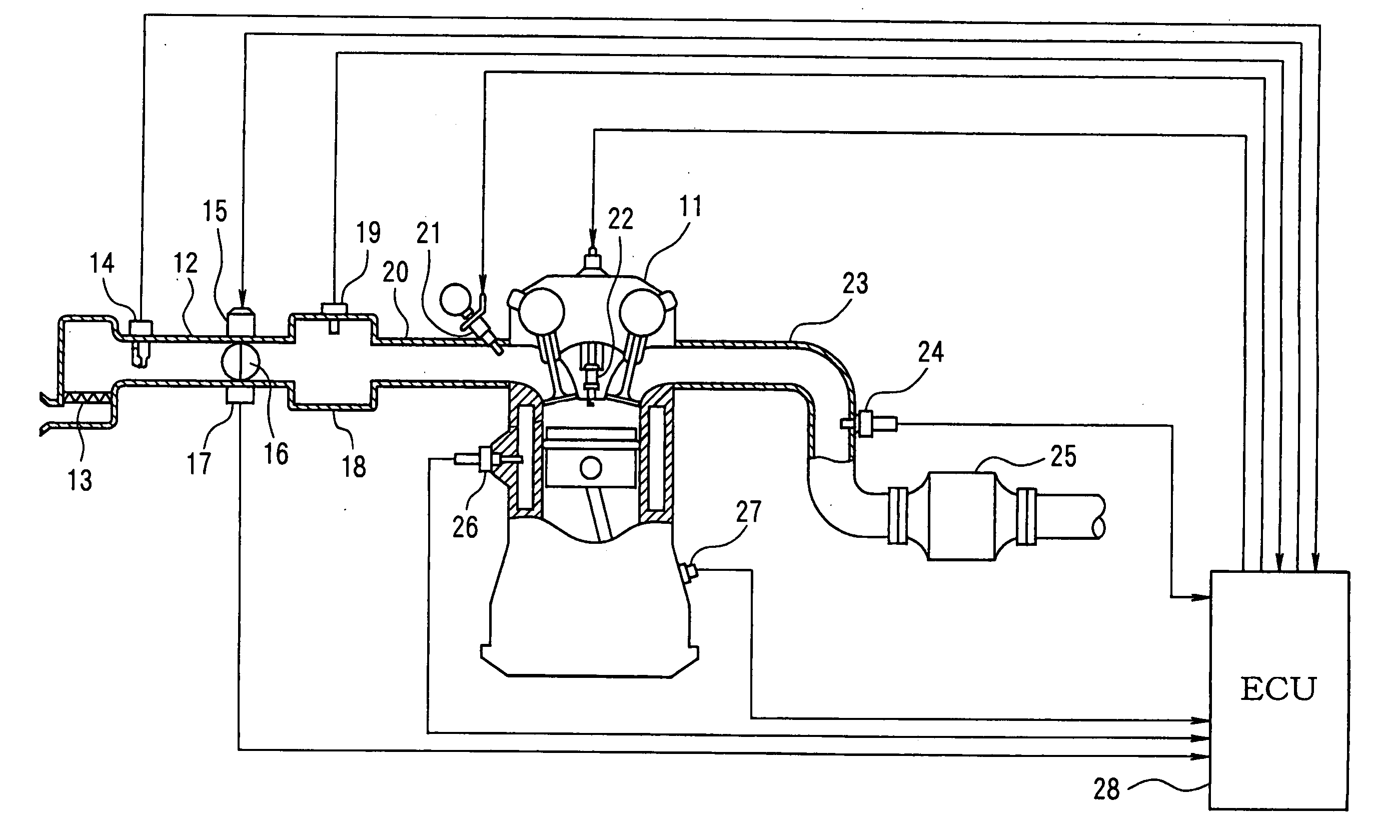
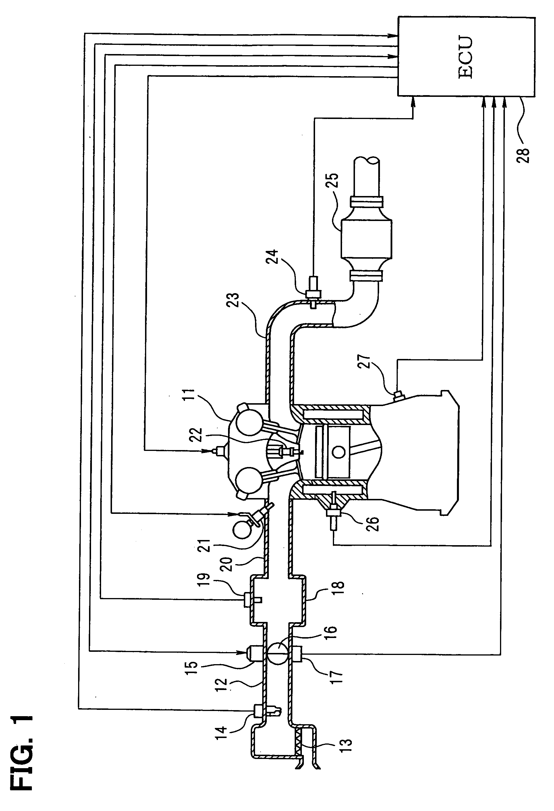
[0033] Referring to FIGS. 1 to 4, the first embodiment described hereinafter. An air cleaner 13 is disposed at most upstream portion of an intake air pipe 12 of the engine 11. An airflow meter 14 (an intake air amount detecting means) detecting an intake air mount is disposed downstream of the air cleaner 13. A throttle valve 16 driving a motor 15 and a throttle position sensor 17 detecting the position of the throttle valve 16 are disposed downstream of the airflow meter 14.

[0034] A surge tank 18 is arranged downstream of the throttle valve 16. An intake air pipe pressure sensor 19 is disposed in the surge tank 18 to detect the intake air pipe pressure. The surge tank 18 is connected with an intake manifold 20 for introducing the intake air into each cylinder of the engine 11. A fuel injector 21 is mounted at the vicinity of an intake air port of the intake manifold 20 corresponding to each cylinder. A spark plug 22 is mounted on the cylinder head of the engine 11 corresponding to...

second embodiment

[0052] Referring to FIGS. 5 and 6, the second embodiment is described. As shown in FIG. 5, an open-loop air-fuel ratio control is performed, in which an estimated throttle-passing-air amount “THest” is calculated, and then the fuel injection amount “Fuel” is calculated based on the estimated cylinder-intake-air amount “Aest” derived based on the estimated throttle-passing-air amount “THest”.

[0053] The ECU 28 performs the estimated throttle-passing-air amount calculating program shown in FIG. 6 to calculate the estimated throttle-passing-air amount. As shown in FIG. 5, the estimated throttle-passing-air amount base value “THbase” is calculated based on the atmospheric pressure, which is referred to as a throttle upstream pressure “P0”, detected by a atmospheric pressure sensor 30, a throttle downstream pressure “Pm” detected by the intake pipe pressure sensor 19, and a throttle position “TA” detected by the throttle position sensor 17, and then a reference throttle-passing-air amoun...

third embodiment

[0065] Referring to FIGS. 7 and 8, a third embodiment is described hereinafter.

[0066] As shown in FIG. 7, an intake air amount “MAF” detected by the airflow meter 14 is adopted as the reference throttle-passing-air amount “THcal”. The estimated throttle-passing-air amount is corrected based on the reference throttle-passing-air amount “THcal”.

[0067] According to the third embodiment, the program shown in FIG. 8 is performed. In step 301, the computer reads the throttle position “TA”, the throttle upstream pressure “P0”, and the throttle downstream pressure “Pm”. In step 302, the estimated throttle-passing-air amount base value “THbase” is calculated based on the throttle position “TA” and the pressure ratio (Pm / P0) according to the above equation (1).

[0068] Then, the procedure proceeds to step 303 in which the intake air amount “MAF” detected by the airflow meter 14 is adopted as the reference throttle-passing-air amount.

THcal=MAF

[0069] In step 304, the base value “THbase” is s...


PUM


Abstract

A computer calculates an estimated cylinder-intake-air amount based on outputs from an airflow meter and a throttle position sensor, and then calculates a reference cylinder-intake-air amount based on an air-fuel ratio in an exhaust gas and fuel injection amount. An error of the estimated cylinder-intake-air amount is calculated by comparing the reference cylinder-intake-air amount with an estimated cylinder-intake-air amount base value. The error is low-pass filtered. The estimated cylinder-intake-air amount base value is corrected to obtain the final estimated cylinder-intake-air amount.

Description

CROSS REFERENCE TO RELATED APPLICATIONS [0001] This application is based on and incorporates herein by reference Japanese Patent Applications No. 2004-202637 filed on Jul. 9, 2004, No. 2005-7143 filed on Jan. 14, 2005 and No. 2005-57584 filed on Mar. 2, 2005, the disclosure of which are incorporated herein by reference. FIELD OF THE INVENTION [0002] The present invention relate to an air-furl controller for an internal combustion engine and a diagnosis apparatus for intake sensors. The internal combustion engine is equipped with a function in which a fuel injection amount is calculated based on an estimated cylinder-intake-air amount according to an open-loop air-fuel ratio control. The diagnosis apparatus detects a malfunction of intake sensors such as an intake air amount sensor and an intake pipe pressure sensor. BACKGROUND OF THE INVENTION [0003] JP-2002-130042A shows a method of calculation of an estimated cylinder-intake-air amount, which is adopted in an open-loop air-fuel ra...

Claims


Application Information

Patent Timeline
IPC IPC(8): F02D41/14
CPCF02D41/18F02D41/222F02D2200/0406F02D2200/0402F02D2200/0404F02D41/2451
Inventor OSUMI, NAOKIMITSUDA, TETSUJIMUKAI, YASUO
Owner DENSO CORP
Why Eureka
Try Eureka