Target tiles in a staggered array

a technology of target tiles and staggered arrays, which is applied in the field of material sputtering, can solve the problems of inability to form such large targets with a single continuous sputter layer, the number of tiles in the tile array may be even greater, and the inability to sputter an aluminum backing plate b>34/b> supporting molybdenum or other tiles,

Inactive Publication Date: 2006-01-12
APPLIED MATERIALS INC
View PDF13 Cites 31 Cited by
  • Summary
  • Abstract
  • Description
  • Claims
  • Application Information

AI Technical Summary

Benefits of technology

[0016] A target, particularly useful as a rectangular target, includes rectangular target

Problems solved by technology

It was often considered infeasible to form such large targets with a single continuous sputter layer.
The number of tiles in the tile array may be even greater if the target material is difficult to work with, such as chromium or molybdenum.
Clearly, sputtering an aluminum backing plate 34 supporting molybdenum or other tiles is not desired.
The rectangular tile arrangement of FIG. 2 presents difficulties with increases in the panel size.
However, with the target and tiles becoming increasingly larger, a transfer fixture grasps the edges of the tiles, and a crane lifts the fixture and moves it to the second table.
Such large mechanical structures are not easily manipulated to provide the desired degree of alignment, specifically, the bonded tiles being separated by no more than 0.5 mm.
If the gap is only slight larger than the plasma dark space, the plasma state in the gap may be unsteady and result in intermittent arcing.
Eve

Method used


Image

  • Target tiles in a staggered array
  • Target tiles in a staggered array
  • Target tiles in a staggered array

Examples


Embodiment Construction

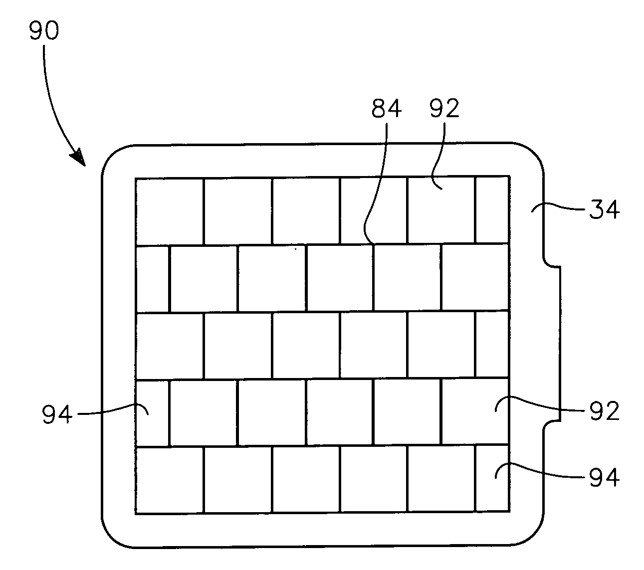
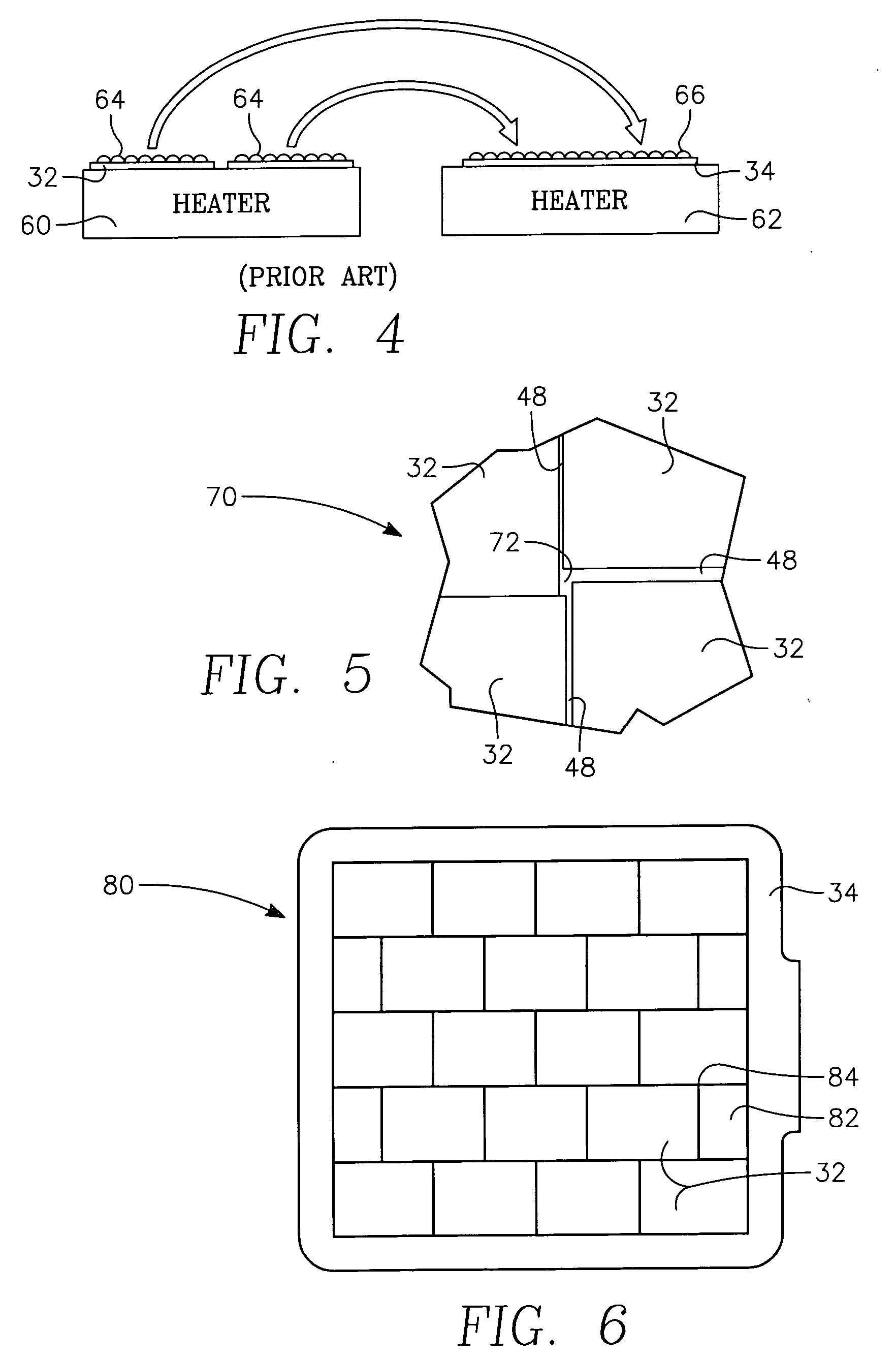
[0035] Targets made according to the invention avoid many of the problems of conventional targets composed of tiles arranged in a rectangular array. Instead, as illustrated in the plan view of FIG. 6, a target 80 of one embodiment of the invention includes rectangular tiles 32 each of substantially the same composition at least on its sputtering face and arranged in staggered rows and bonded to the target backing plate 34. In this embodiment, the tiles 32 of one row are offset in the row direction from the tiles 32 of the neighboring rows. In some of the rows, end tiles 82 have a length in the row direction that is only a fraction of the corresponding length of full tiles 32. In this embodiment, it is preferred that the length of the end tiles 82 be one-half the full length less the desired size of the gap between tiles so that only two sizes of tiles 32, 82 are needed. While the tiles 32, 82 can still slide in the row direction during their transfer to and bonding with the backing ...


PUM

PropertyMeasurementUnit
Lengthaaaaaaaaaa
Lengthaaaaaaaaaa
Fractionaaaaaaaaaa

Abstract

A sputtering target, particularly for sputter depositing a target material onto large rectangular panels, in which a plurality of target tiles are bonded to a backing plate in a two-dimensional non-rectangular array such that the tiles meet at interstices of no more than three tile, thus locking the tiles against excessive misalignment during bonding and repeated thermal cycling. The rectangular tiles may be arranged in staggered rows or in a herringbone or zig-zag pattern. Hexagonal and triangular tiles also provide many of the advantages of the invention. Sector-shaped tiles may be arranged in a circular target with a staggered offset at the center.

Description

RELATED APPLICATION [0001] This application is a continuation in part of Ser. No. 10 / 888,383, filed Jul. 9, 2004, incorporated herein by reference.FIELD OF THE INVENTION [0002] The invention relates generally to sputtering of materials. In particular, the invention relates to the a target containing multiple tiles of target material. BACKGROUND ART [0003] Sputtering, alternatively called physical vapor deposition (PVD), is widely used in the commercial fraction of semiconductor integrated circuits for depositing layers of metals and related materials. A typical DC magnetron plasma reactor 10 illustrated in cross section in FIG. 1 includes an electrically grounded vacuum chamber 12 to which a target 14 is vacuum sealed through an electrical isolator 16. A DC power supply 18 negatively biases the target 14 with respect to the chamber 12 or to a grounded sputter shield within the chamber 12 to excite an argon sputter working gas into a plasma. However, it is noted that RF sputtering is...

Claims


Application Information

Patent Timeline
IPC IPC(8): C23C14/00C23C14/34
CPCH01J37/3423C23C14/3407C23C14/34H01L21/67207C23C14/14G02F1/13C23C14/3464H01L2924/13069H01L21/02631
Inventor TEPMAN, AVI
Owner APPLIED MATERIALS INC
Why Eureka
Try Eureka