Optical lens system and method for microfluidic devices

a microfluidic device and optical lens technology, applied in the field of microfluidic techniques, can solve the problems of inability to meet the performance goals of conventional scanning and stitching systems, cumbersome and less efficient operators, and other operator errors and limitations, and achieve the effects of reducing or eliminating synchronization problems, high nas, and large field of view

Active Publication Date: 2006-01-12
STANDARD BIOTOOLS INC
View PDF70 Cites 170 Cited by
  • Summary
  • Abstract
  • Description
  • Claims
  • Application Information

AI Technical Summary

Benefits of technology

[0038] Some embodiments of the present invention provide imaging systems in which the area of the microfluidic device is imaged all at once. In an embodiment in which 10 seconds per image is available, several seconds of integration time are available. Synchronization problems are reduced or eliminated as data is collected from all the pixels at the same time. Moreover, embodiments of the present invention generally illuminate the entire microfluidic device (˜31 mm×3 mm area) at once and utilize lens systems with high NAs and a large field of view. As described throughout the present specification, embodiments of the present invention provide methods and systems that are less complex and more powerful than conventional systems. Depending upon the embodiment, one or more of these limitations may be overcome by the present methods and systems according to embodiments of the present invention. Further details of the present invention may be found throughout the present specification and more particularly below. Depending upon the embodiment, one or more of these benefits may exist. These and other benefits have been described throughout the present specification and more particularly below.

Problems solved by technology

A goal to make such micro-sized devices arises from significant benefits achieved from miniaturization of conventional macro scale analyses and syntheses, which are often cumbersome and less efficient.
Automated systems also decrease operator errors and other operator type limitations.
Conventional scanning and stitching systems are not able to meet these performance goals.
In addition to slowing system throughput, these scanning and stitching system can limit the potential for utilizing certain assays, e.g., performance of real-time PCR.

Method used


Image

  • Optical lens system and method for microfluidic devices
  • Optical lens system and method for microfluidic devices
  • Optical lens system and method for microfluidic devices

Examples


Embodiment Construction

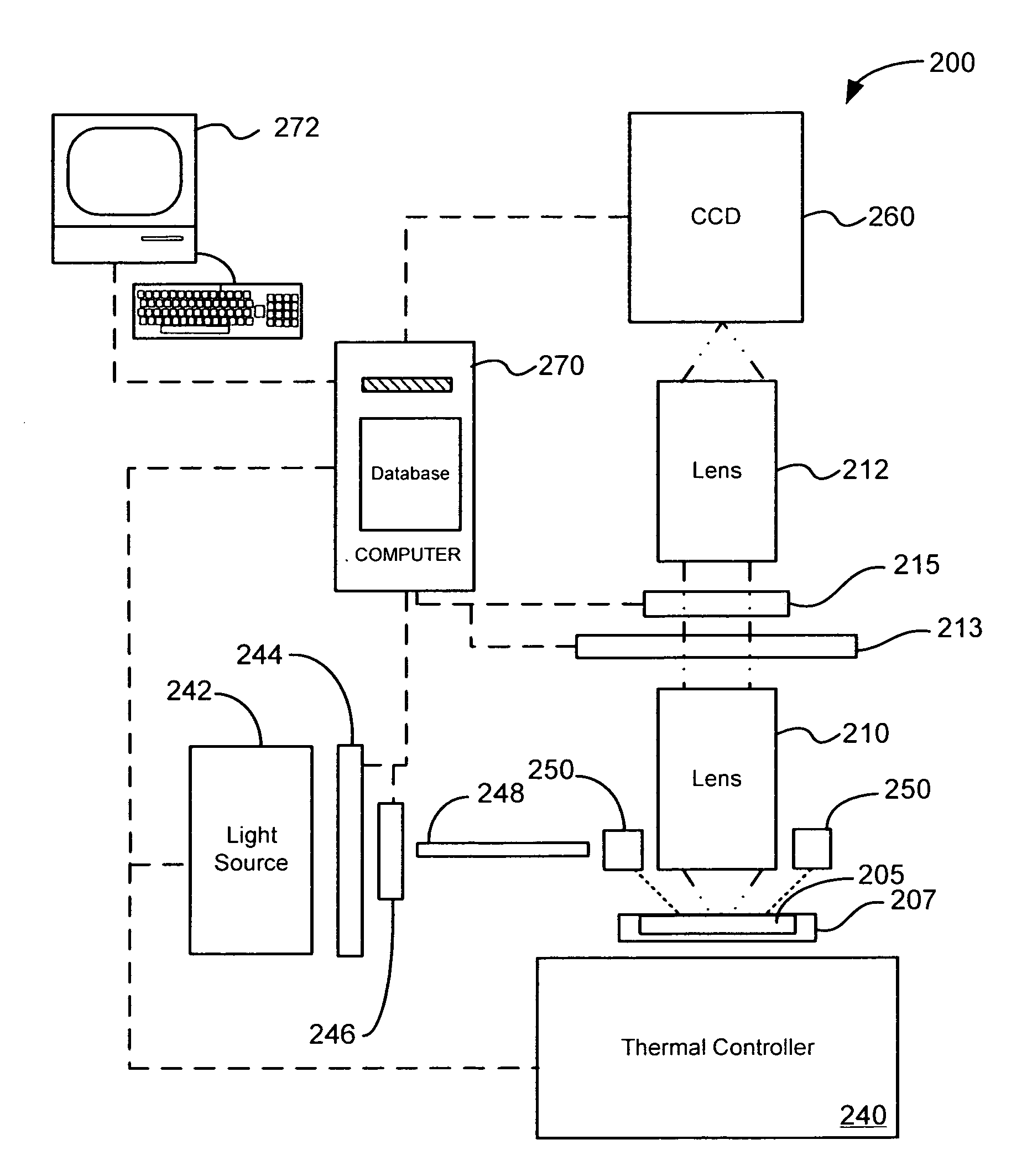
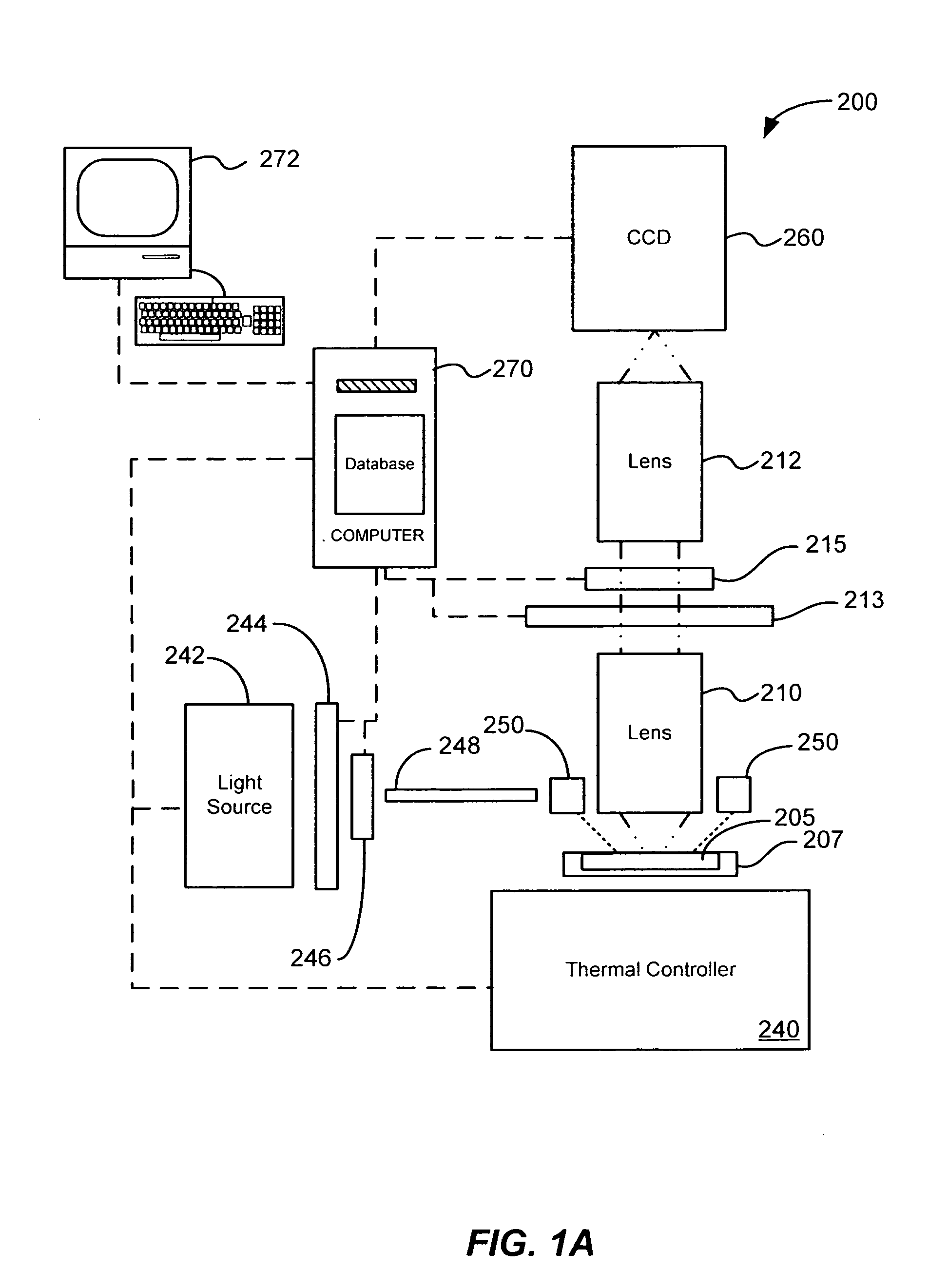
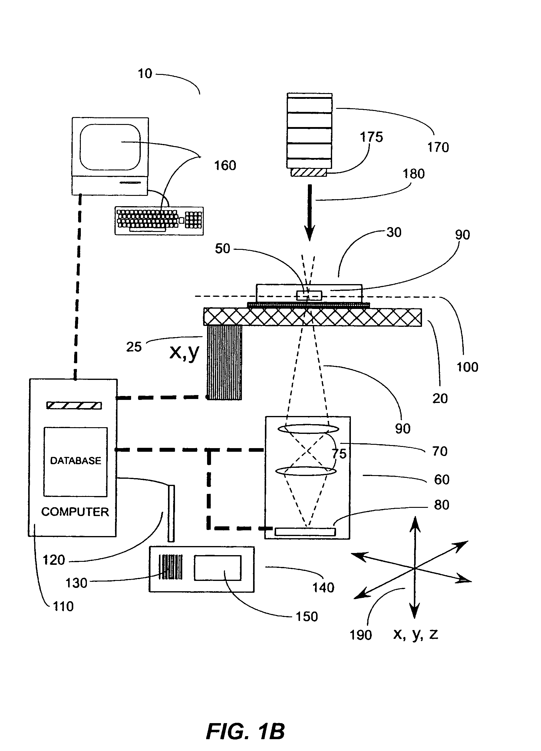
[0056] According to the present invention, techniques for microfluidic systems are provided. In particular, the invention provides a method and system for imaging one or more entities suspended in a volume of fluid in a chamber of a microfluidic device. More particularly, the present method and system for imaging uses indications from a fluorescence signal associated with the one or more entities in the microfluidic device. Merely by way of example, the techniques for microfluidic methods and systems are applied using fluorescent, chemiluminescent, and bioluminescent readers coupled to the microfluidic device, but it would be recognized that the invention has a much broader range of applicability.

[0057] In the present application, references are made to certain types of “reaction” chambers in a microfluidic device. In general, these “reaction chambers” include processing sites, processing chambers, and / or reaction sites, any combination of these, and the like. These chambers may be...


PUM

PropertyMeasurementUnit
timeaaaaaaaaaa
timeaaaaaaaaaa
timeaaaaaaaaaa

Abstract

An apparatus for imaging one or more selected fluorescence indications from a microfluidic device. The apparatus includes an imaging path coupled to least one chamber in at least one microfluidic device. The imaging path provides for transmission of one or more fluorescent emission signals derived from one or more samples in the at least one chamber of the at least one microfluidic device. The chamber has a chamber size, the chamber size being characterized by an actual spatial dimension normal to the imaging path. The apparatus also includes an optical lens system coupled to the imaging path. The optical lens system is adapted to transmit the one or more fluorescent signals associated with the chamber.

Description

CROSS-REFERENCES TO RELATED APPLICATIONS [0001] This application claims priority to U.S. Provisional No. 60 / 578,106, filed Jun. 7, 2004, which is incorporated by reference herein for all purposes.BACKGROUND OF THE INVENTION [0002] The present invention relates generally to microfluidic techniques. In particular, the invention provides a method and system for imaging one or more entities in a chamber of a microfluidic device (e.g., suspended in a volume of fluid). More particularly, the present method and system for imaging uses indications from a fluorescence signal associated with the one or more entities in the microfluidic device. Merely by way of example, the techniques for microfluidic methods and systems are applied using fluorescent, chemiluminescent, and bioluminescent readers coupled to the microfluidic device, but it would be recognized that the invention has a much broader range of applicability. [0003] Concerted efforts to develop and manufacture microfluidic systems to ...

Claims


Application Information

Patent Timeline
Patent Type & Authority Applications(United States)
IPC IPC(8): G01N27/26B01L3/00B01L7/00G01N27/447G02B21/02G02B21/16
CPCG01N21/8483G02B21/16B01L7/52G01N21/6456B01J2219/00576B01J2219/00704G01N27/44721B01L3/5027G01N21/6452G01N2021/6421G01N21/6486C12Q1/686G01N21/64G01N21/75G01N2201/061G02B21/36
Inventor UNGER, MARC A.
Owner STANDARD BIOTOOLS INC
Why Eureka
Try Eureka