Earthing switch

a technology for earpieces and switches, applied in the field of earpiece switches, can solve the problems of inconvenient structure, easy insertion, and inability to ensure optimal contact pressure, and achieve the effects of high reliability, easy assembly, and convenient manufacturing

Inactive Publication Date: 2006-01-12
ABB (SCHWEIZ) AG
View PDF8 Cites 6 Cited by
  • Summary
  • Abstract
  • Description
  • Claims
  • Application Information

AI Technical Summary

Benefits of technology

[0012] Yet a further object of the present invention is to provide an earthing switch with a reduced number of components which can be easily assembled both each other and with the switchgear in which

Problems solved by technology

Prior to earthing the line or bus terminals, it is mandatory to disconnect the upstream source of electrical power supplying the switchgear assembly; however, under certain conditions, it may happen by mistake to ground a live circuit.
Another dangerous situation arises when the upstream source of electrical power is inadvertently reenergized during bus maintenance before performing closing of the switch.
In fact, in many cases they have a structure that is not suitable for assuring an optimised functionality of the earthing switch; in particular it does not assure an optimised co

Method used


Image

  • Earthing switch
  • Earthing switch
  • Earthing switch

Examples


first embodiment

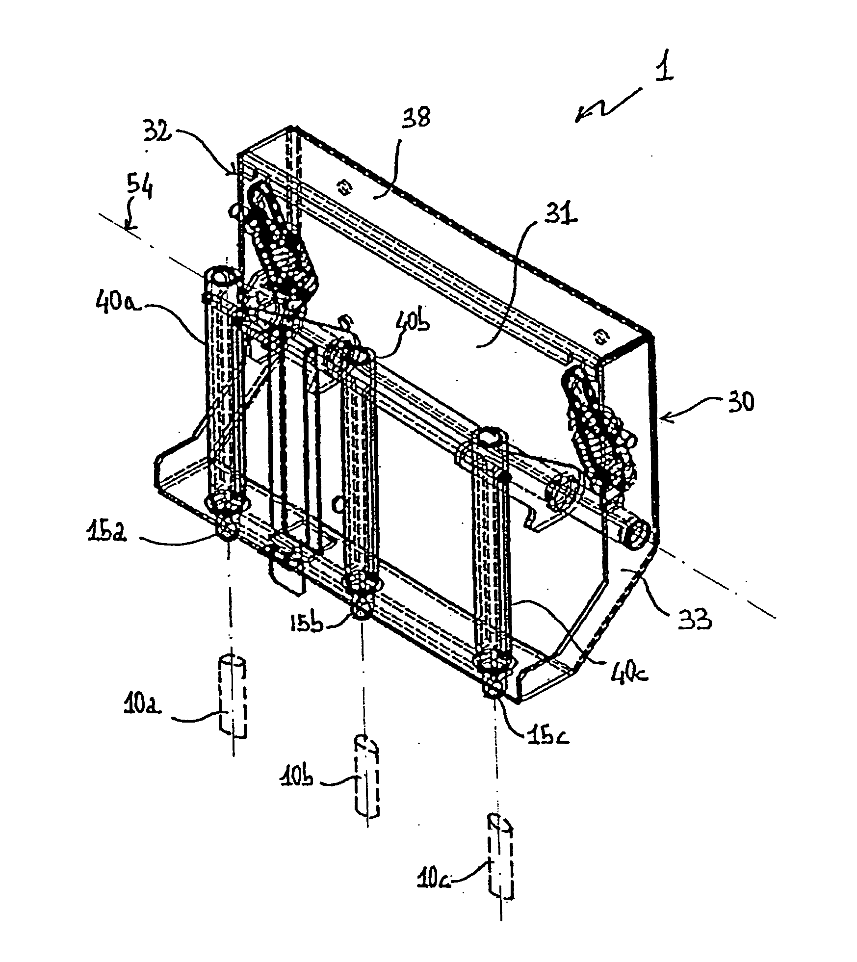
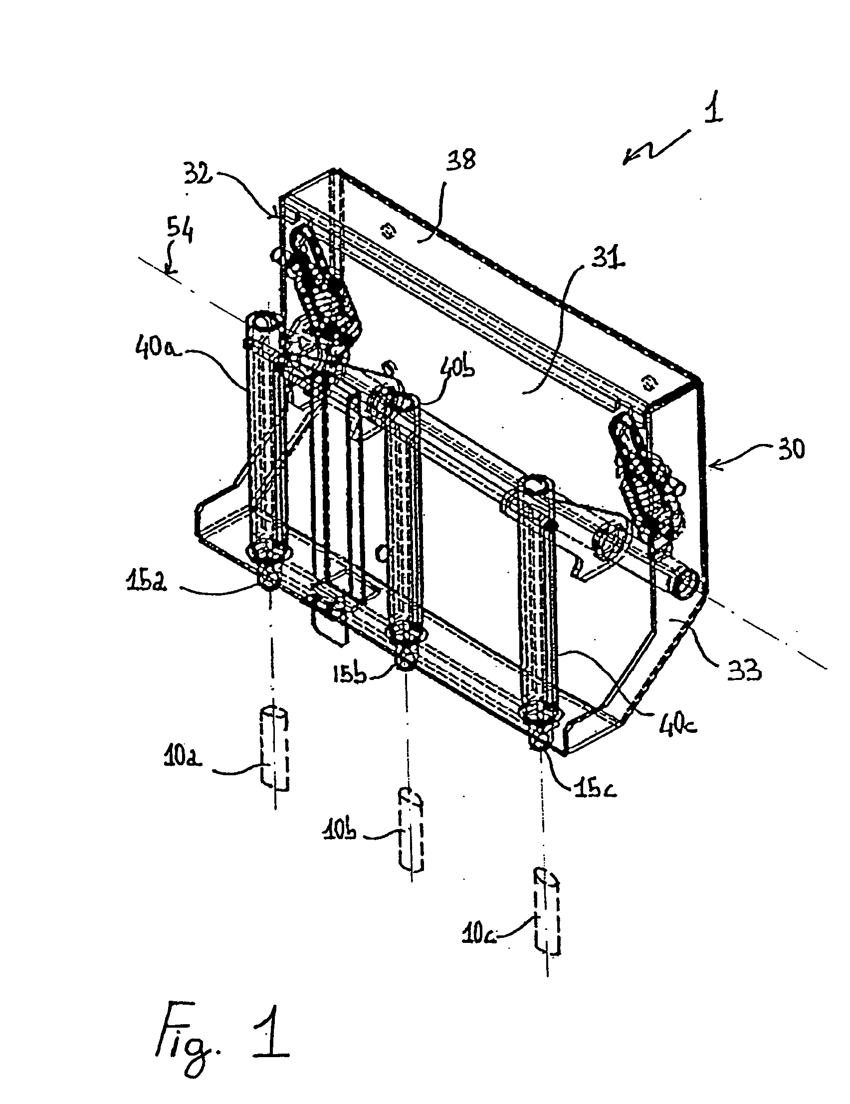
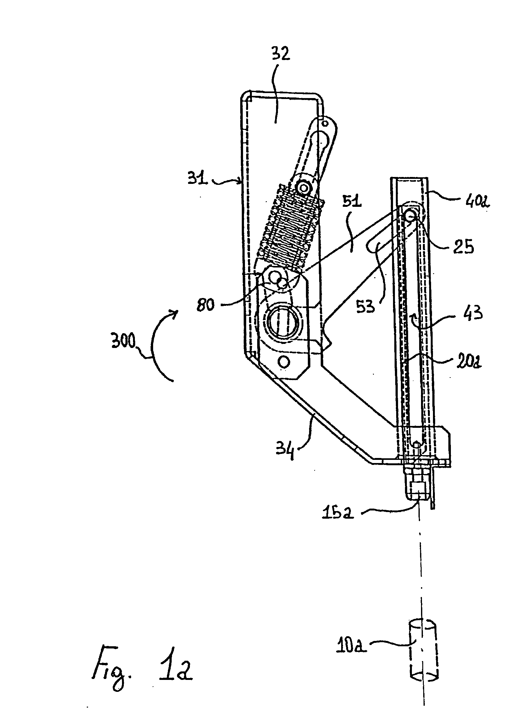
[0031] Preferably, the earthing switch 1 according to the present invention comprises a plurality of rectilinear guides each having a fixed element 40a, 40b, 40c coaxially coupled to a corresponding moving element 20a, 20b, 20c. In particular, in a first embodiment illustrated in FIGS. 1-2, each guide comprises a fixed element 40a, 40b, 40c coaxially coupled to a respective moving element 20a, 20b, 20c and each of the moving elements 20a, 20b, 20c bears, at one end, a corresponding movable contact surface 15a, 15b, 15c suitable to contact a respective fixed contact 10a, 10b, 10c when the switch 1 is brought into the closed condition. Further, it is advantageously provided a cross bar 26 which is connected to said moving elements 20a, 20b, 20c at an end thereof and electrically connects each other the plurality of movable contact surfaces 15a, 15b. This cross bar 26 can comprise, for example, a copper bar which is fastened near the ends of the moving elements 20a, 20b, 20c; advantage...

second embodiment

[0032] In the second embodiment illustrated in FIGS. 3-3a, the earthing switch 1 comprises a plurality of rectilinear guides, for example two, each comprising a fixed element 40a, 40b, 40c coaxially coupled to a respective moving element 20a, 20b, 20c, and a cross bar 26 which is positioned transversally with respect to the moving elements 20a, 20b, 20c and is directly connected to them; advantageously, in this embodiment the movable contact surfaces are constituted by parts 15a, 15b, 15c of the cross bar 26 itself, spaced apart from each other along its extension, which parts contact each a respective fixed contact 10a, 10b, 10c when the switch 1 is in the closed condition. Also in this case the cross bar 26 allows performing an earthing operation without damaging the equipment if the earthing switch 1 is closed before disconnecting the upstream power source.

[0033] As illustrated, in both embodiments the guides can be preferably realized, for example, by tubular fixed elements 40a,...


PUM


Abstract

An earthing switch for a medium voltage switchgear comprising a plurality of fixed contacts, a plurality of movable contact surfaces which are suitable to contact said plurality of fixed contacts and a support structure suitable to support moving means which allow the movement of said second plurality of contact surfaces. The earthing switch comprises at least one guide which comprises a fixed element and a moving element coaxially coupled therewith, said moving element being operatively connected to said movable contact surfaces so as to allow their movement along a substantially rectilinear direction from a first position, corresponding to an open condition of said switch, to a second position corresponding to a closed condition of said switch.

Description

FIELD OF THE INVENTION [0001] The present invention relates to an earthing switch which can be used preferably in medium voltage switchgear assemblies, normally for voltages ranging between 1 and 36 kV. BACKGROUND OF THE INVENTION [0002] Switchgear assemblies are typically used to connect a plurality of electrical loads to a common electrical bus. Such assemblies are typically provided with a plurality of switching devices having one side connected to the common bus and the other side connected to various electrical loads; these switching devices provide electrical protection to isolate the loads during abnormal current conditions, such as an overload or a short circuit condition. [0003] Switchgear often comprises an earthing switch which allows either the line or bus terminals to be grounded for personnel safety. That is particularly important during maintenance operations, but also during normal function of the switchgear assemblies. Prior to earthing the line or bus terminals, it...

Claims


Application Information

Patent Timeline
IPC IPC(8): H01H33/18
CPCH01H3/30H01H31/003H01H33/6661H01H33/022H01H31/32H02B11/28
Inventor CORTI, DAVIDE
Owner ABB (SCHWEIZ) AG
Why Eureka
Try Eureka