Method and apparatus for repairing or building up surfaces on a workpiece while the workpiece is mounted on a machine tool

a technology for building up surfaces and workpieces, which is applied in the direction of soldering apparatus, turbines,auxillary welding devices, etc., can solve the problems of large equipment required to accomplish inability to easily achieve arc welding or torch heating, and the necessity of having the workpiece separated from the tabl

Inactive Publication Date: 2006-01-12
INGERSOLL MACHINE TOOLS
View PDF6 Cites 41 Cited by
  • Summary
  • Abstract
  • Description
  • Claims
  • Application Information

AI Technical Summary

Problems solved by technology

Processes such as arc welding or torch heating, for example, cannot readily be accomplished while the workpiece is mounted on the table of a machine tool, without fear of damage to the workpiece, the table and / or machine tool from the electrical currents or fields, high temperatures, or massive amounts of heat generated by such prior approaches.
With other prior approaches, such as stir friction welding of metals, or friction welding of thermoplastics, the equipment required to accomplish these processes is typically too large, or otherwise not amenable to performing the material addition process while the workpiece is mounted on a machine tool of the type used for subsequent machining of the workpiece.
The necessity of having the workpiece separated from the table of the machine tool during build up of the surface is especially bothersome in the case of a repair to a workpiece necessitated by a mistake during a machining operation, where too much material has been erroneously removed, where a hole has been drilled in a wrong location, or where a bore has been made too large, for example.
Whenever a workpiece is removed from a machine tool, it is typically also necessary to once again “indicate in” the workpiece after it is reinstalled on the machine tool, thereby adding further wasted time and effort to the process of effecting the repair.
Such scanning and measurement may require additional set up and working time.

Method used


Image

  • Method and apparatus for repairing or building up surfaces on a workpiece while the workpiece is mounted on a machine tool
  • Method and apparatus for repairing or building up surfaces on a workpiece while the workpiece is mounted on a machine tool
  • Method and apparatus for repairing or building up surfaces on a workpiece while the workpiece is mounted on a machine tool

Examples


Embodiment Construction

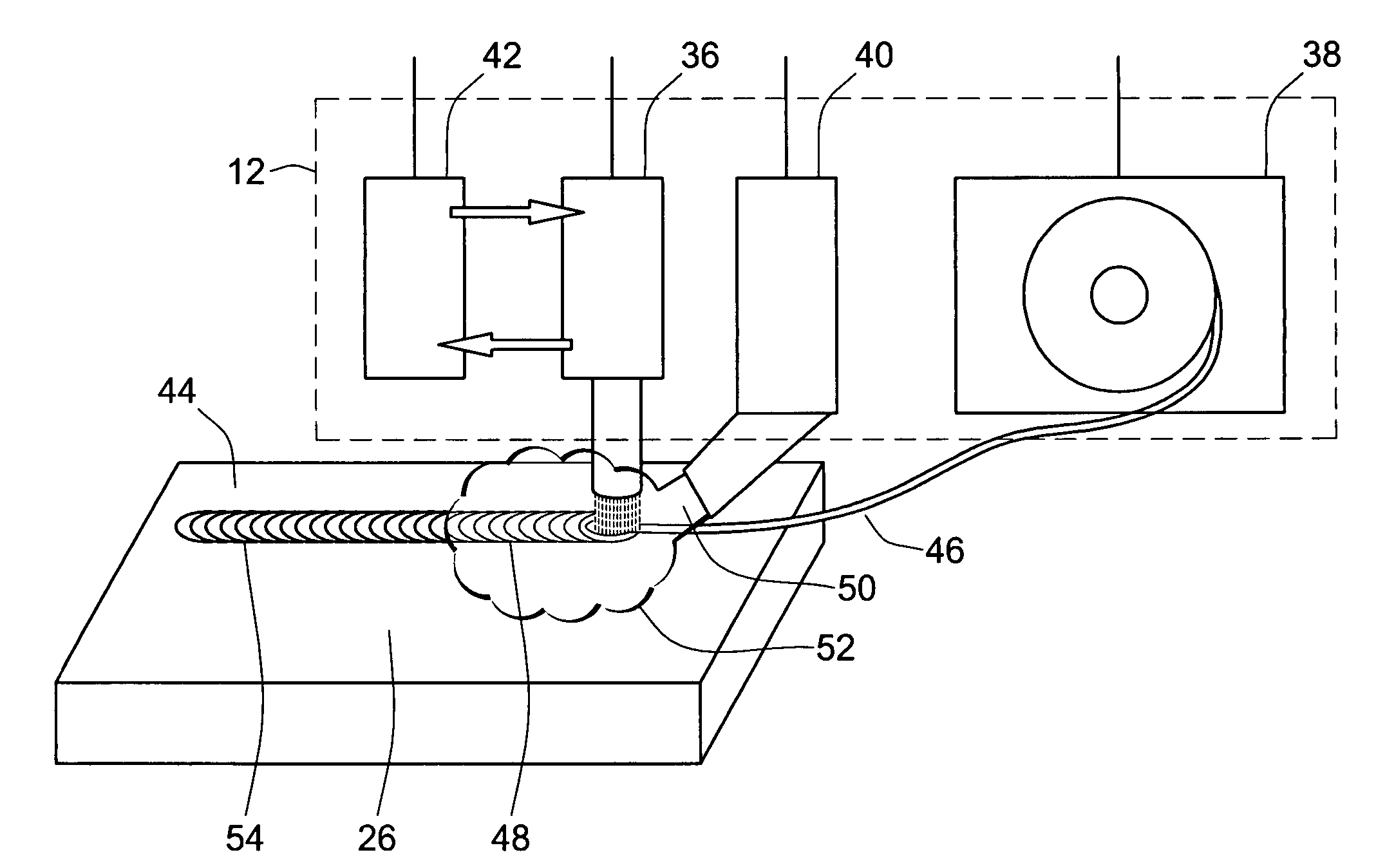
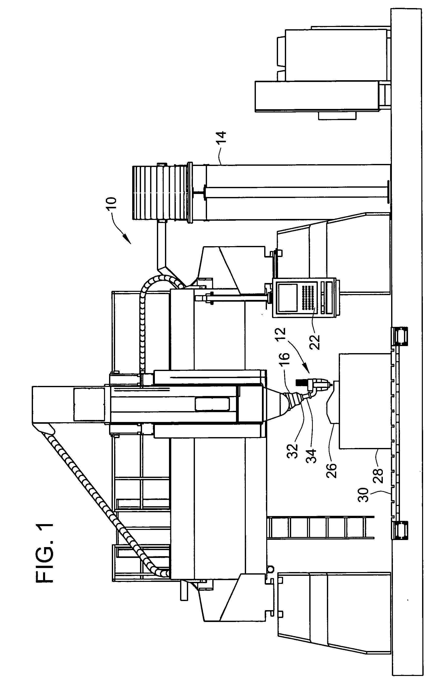
[0025]FIG. 1 shows an exemplary embodiment of the invention in the form of a machining apparatus 10 including a material addition device 12 operatively attached to a machine tool 14. As shown in FIG. 5, in the exemplary embodiment, the material addition device 12 includes a wire feeder 38, a laser 36, and associated cooling and inert gas supplying elements 42, 40, as will be explained in greater detail below.

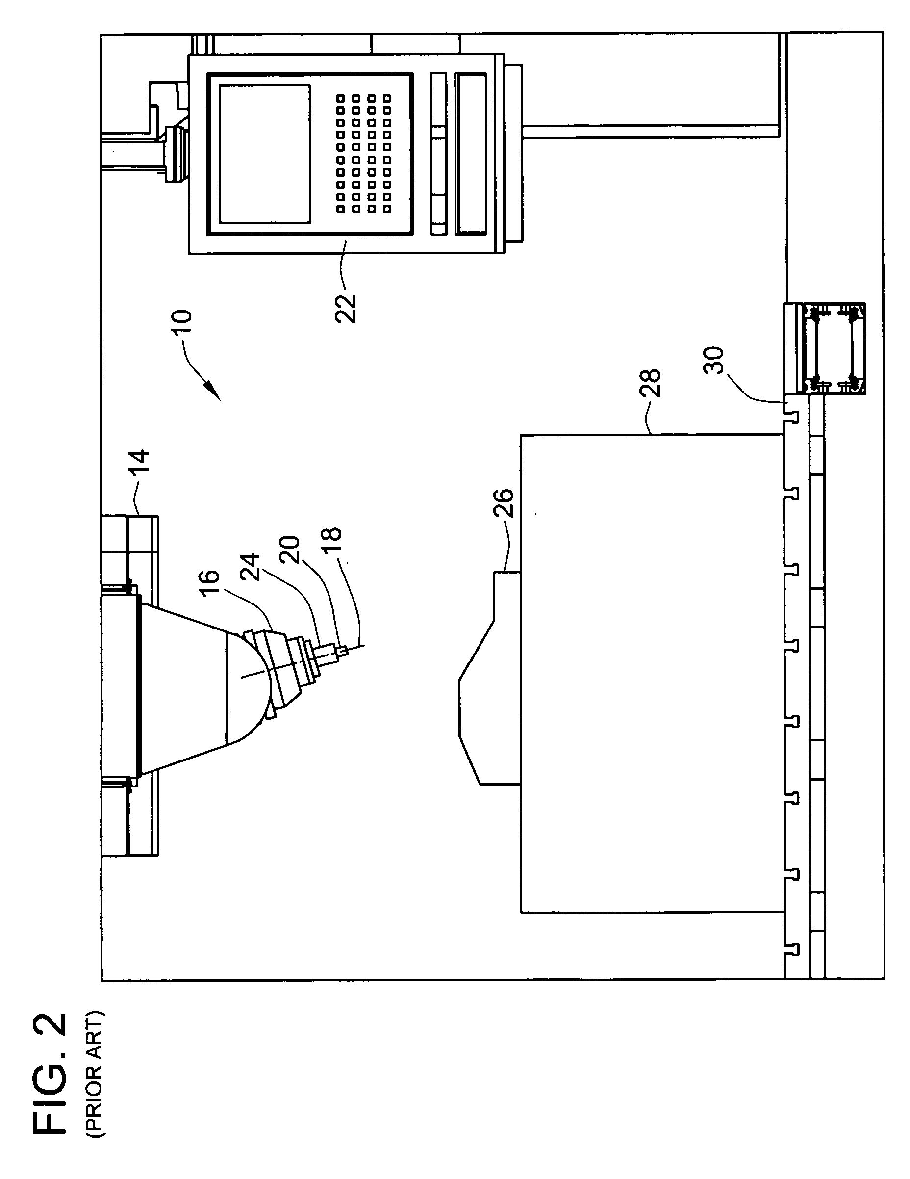
[0026] The machine tool 14 in the exemplary embodiment is a high velocity gantry, of the type used in the die and mold industry for machining dies of the type used for forming automotive body panels. As shown in FIGS. 1 and 2, and Attachment 1, the machine tool 14 includes a nutating spindle unit 16 with a built in rotary axis 18 that provides 5-axis contour machining with large diameter face mills or end mills 20, when controlled by a controller 22 of the machine tool 14. The end mill 20 is held in a collet 24 which is adapted for automated insertion into and retention in the ...


PUM

PropertyMeasurementUnit
lengthaaaaaaaaaa
widthaaaaaaaaaa
areaaaaaaaaaaa

Abstract

A method and apparatus are provided for adding material to a workpiece mounted on a machine tool, while the workpiece is mounted on a machine tool, by melting a portion of the workpiece, in a zone of addition of the workpiece, using a material addition device including a laser, to form a puddle of molten material of the workpiece in the zone of addition, and feeding the material to be added into the puddle of molten material while continually applying heat with the laser. The melting and feeding are performed while the workpiece remains mounted in the same set-up that is used for machining the workpiece on the machine tool, except for replacing machining cutters used during machining operations with the material addition device. The machine tool may be a lathe, a grinder, a milling machine, a jig bore, or any other type of machine tool.

Description

CROSS REFERENCE TO RELATED PATENT APPLICATIONS [0001] This patent application claims benefit of U.S. provisional patent application 60 / 586,823, filed on Jul. 9, 2004, the entire disclosure of which is incorporated herein by reference.FIELD OF THE INVENTION [0002] This invention relates generally to fabrication and / or repair of workpieces by processes involving machining operations performed on the workpiece while it is attached to a standard table of a machine tool, and more particularly to fabrication and / or repair of workpieces wherein a surface of a workpiece must be built-up, during a fabrication or repair sequence, by heating an area of the substrate to form a molten puddle and melting additional material into the puddle, to form a built-up portion of the workpiece which is subsequently machined with the workpiece mounted on the table of a machine tool. BACKGROUND OF THE INVENTION [0003] There are many instances where it is necessary to repair or build up a surface of a workpie...

Claims


Application Information

Patent Timeline
Patent Type & Authority Applications(United States)
IPC IPC(8): B23K26/26B23K26/34
CPCB23K26/10B23K26/123B23K26/1458B23K26/203B23K37/0235B23K2201/001B23K26/345B23P6/007F01D5/005F05D2230/234F05D2230/80B23K26/3206B23K26/3246B23P6/00B23K26/1462B23K26/211B23K26/32B23K26/324B23K26/342B23K2101/001B23K2103/30B23K2103/50B23P23/04B33Y30/00
Inventor OLDANI, TINO
Owner INGERSOLL MACHINE TOOLS
Why Eureka
Try Eureka