Automatic cutting machine having receiving device for lens

a technology of receiving device and automatic cutting machine, which is applied in the direction of manufacturing tools, grain treatment, transportation and packaging, etc., can solve the problems of unstable lens quality, reduced production efficiency, and increased cost, and achieves rapid lens removal and significant increase in production efficiency.

Inactive Publication Date: 2006-01-12
ASIA OPTICAL CO INC
View PDF11 Cites 13 Cited by
  • Summary
  • Abstract
  • Description
  • Claims
  • Application Information

AI Technical Summary

Benefits of technology

[0009] Accordingly, one object of the present invention is to provide an automatic cutting machine that facilitates operation, occupies a small space, realizes integration of cutting and packaging, and ensures reliable and efficient output of high-quality products.
[0010] Another object of the present invention is to provide a lens cutting device that increases cutting efficiency and lens yield.
[0011] A further object of the present invention is to provide an automatic cutting machine having a take out device for lens. The take out device ensures rapid take out of lens to increase production efficiency, and also prevents the lens from contamination or damage.

Problems solved by technology

This results in increased cost.
This reduces production efficiency and provides unstable lens quality due to the operator's skill level.
Additionally, with the rapid development of the technology, lenses used in consuming products, such as mobile phones, are becoming increasingly smaller.
This also makes manual cutting more and more difficult and unpractical.
However, as the cupula of the robotic arm of the conventional automatic cutting machine keeps intimate contact with the lens during the sucking process, the lens may be damaged.
In addition, the multi-axis mechanism, positioning portion and control device applied by the conventional automatic cutting machine are rather complex and bulky, which also increases cost and occupies a large space.

Method used


Image

  • Automatic cutting machine having receiving device for lens
  • Automatic cutting machine having receiving device for lens
  • Automatic cutting machine having receiving device for lens

Examples


Embodiment Construction

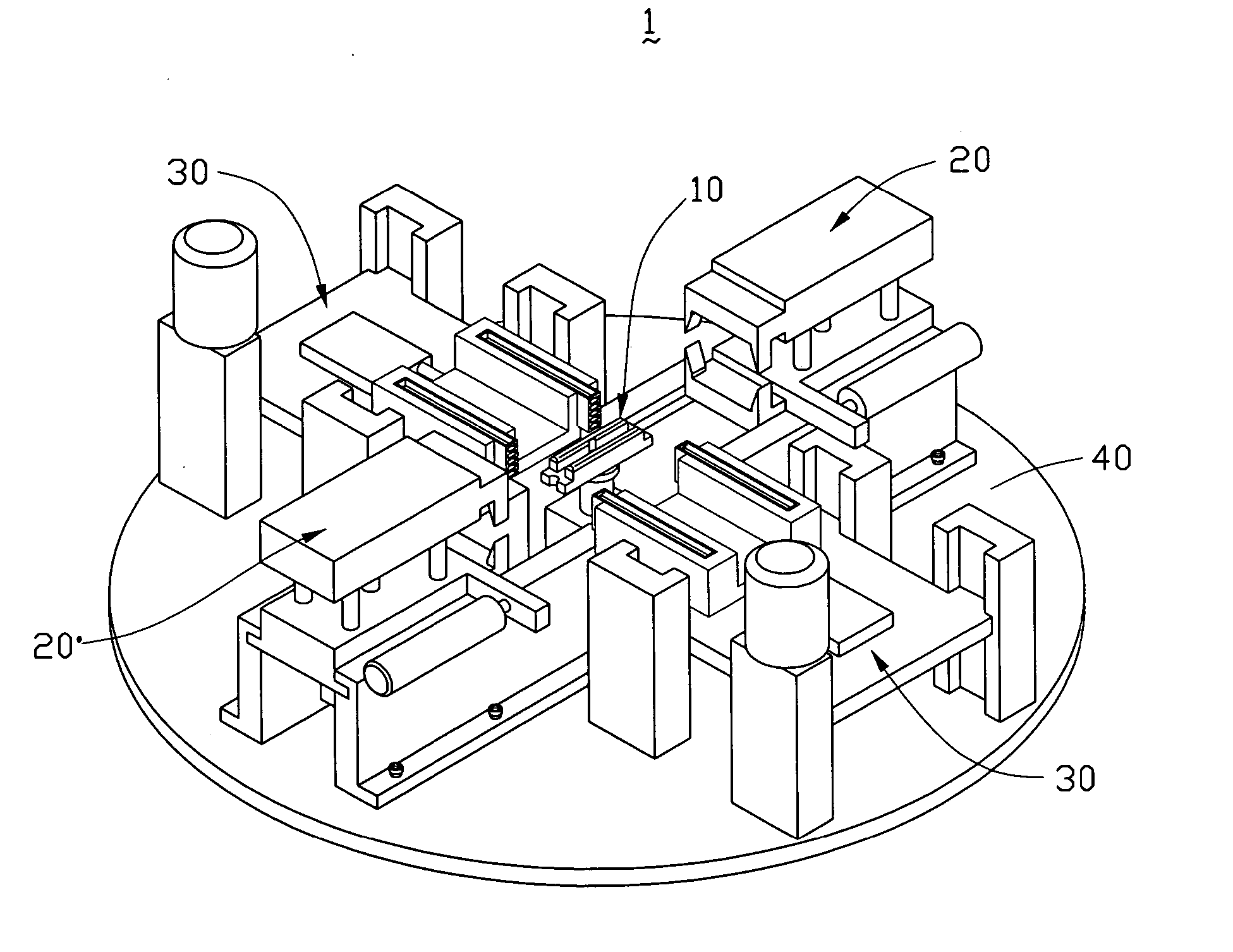
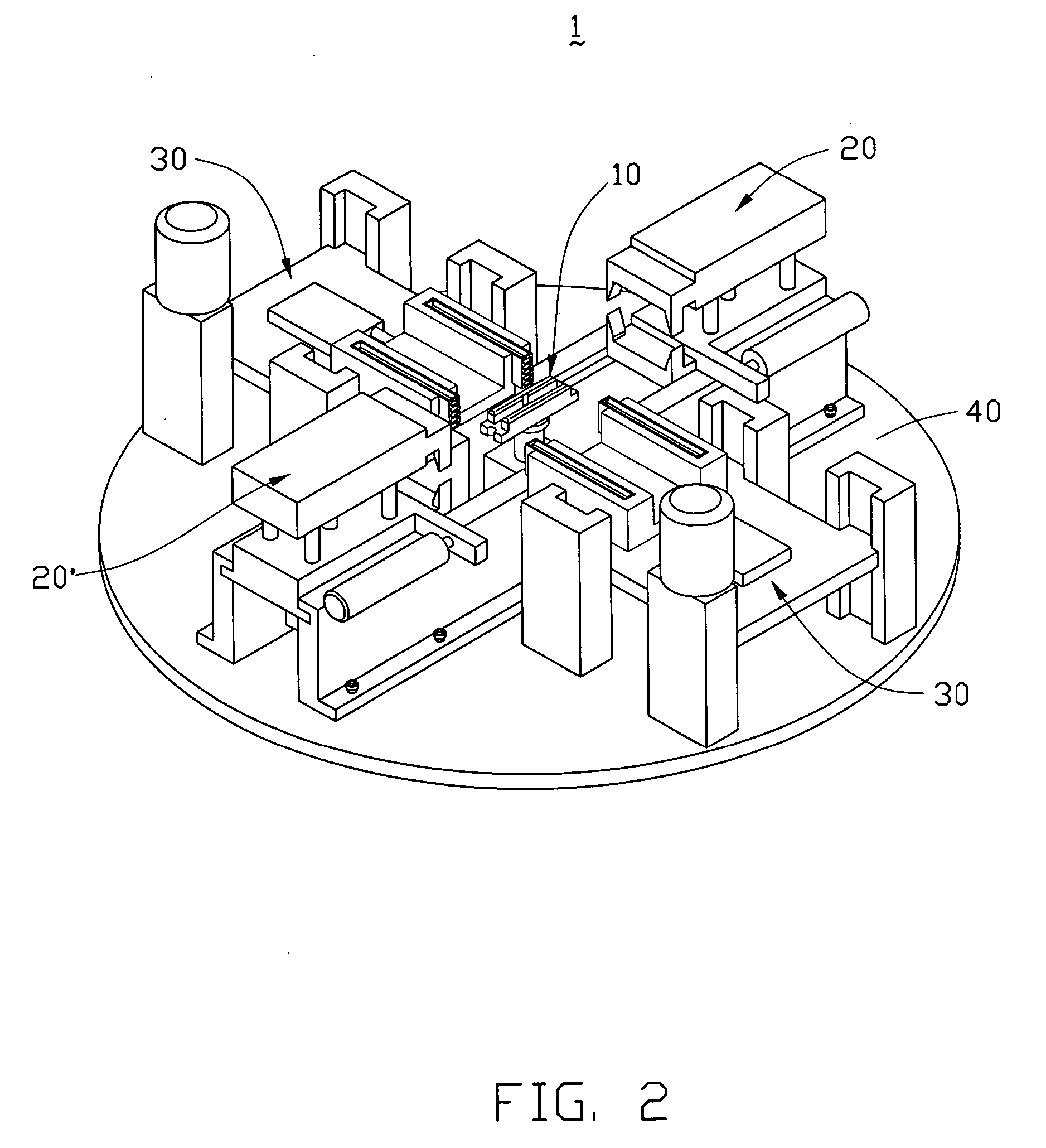
[0035] Referring to FIG. 2, an automatic cutting device 1 in accordance with the present invention comprises a carrying device 10, a cutting device 20, a take out device 30, a body portion where these devices are mounted, and an electrical control portion for controlling the operation of these devices. The body portion includes a base 40, a power supply unit and other accessory equipments. The electrical control portion comprises programmable logic controllers, relays and other accessory circuits. Since the inventive features of the present invention lie on the integrated configuration of the carrying device 10, the cutting device 20 and the take out device 30, and the corresponding cutting method thereof, a detailed description of the related conventional devices, such as accessory equipments and circuits, will be omitted herein.

[0036] As shown in FIGS. 3A and 3B, the carrying device 10 comprises a shelf 11 secured to the base 40 by bolts 50, a receptacle 12 for receiving a semi-f...


PUM

PropertyMeasurementUnit
poweraaaaaaaaaa
temperatureaaaaaaaaaa
transparencyaaaaaaaaaa

Abstract

An automatic lens cutting machine (1) includes a body portion, a carrying device (10), a cutting device (20), a take out device (30), a power device and an electrical control portion. The take out device is mounted adjacent to the carrying device, and comprises a shelf (31) mounted on a base (40) of the body portion and a lens receiving device (34) disposed above the shelf. The lens receiving device has a plurality of rows of tubular rings. Each row has a plurality of rings. The rings receive unseparated lenses (90) on a semi-finished lens assembly (9) therein when the automatic lens cutting machine is in operation, and retain the separated lenses therein after the semi-finished lens assembly is subject to a cutting operation.

Description

BACKGROUND OF THE INVENTION [0001] 1. Field of the Invention [0002] The present invention relates to an automatic cutting machine, and particularly relates to an automatic cutting machine having a receiving device for lens. [0003] 2. Description of Prior Art [0004] Materials employed in the generating of lenses are basically those of glass (inorganic) or plastic (organic) compounds. As an inorganic material, glass has excellent transparency. However, to obtain an optical lens, the glass substrate must be subject to a plurality of processes, such as coarse grind, fine grind and polish processes. This results in increased cost. Accordingly, a plastic material, such as polycarbonate, is generally used for optical lenses. Polycarbonate lenses are the most-used alternative material for modem consuming product lenses. The polycarbonate lens is thinner, lighter, and provides greater impact resistance, high refractive index, complete UV protection, heat resistance and easy processability. [...

Claims


Application Information

Patent Timeline
Patent Type & Authority Applications(United States)
IPC IPC(8): B26F3/02B26D1/09B26D7/10B29C45/38
CPCB26D7/10B26D1/09Y10T83/447Y10T83/4577Y10T83/464Y10T83/6584Y10T83/7573Y10T83/819Y10T83/8737Y10T83/8748Y10T83/9447Y10T225/22
Inventor CHOU, LEE JUNGLIANG, LIU ZHONG
Owner ASIA OPTICAL CO INC
Why Eureka
Try Eureka