Projection type display device

Active Publication Date: 2006-01-12
SONY CORP
View PDF7 Cites 12 Cited by
  • Summary
  • Abstract
  • Description
  • Claims
  • Application Information

AI Technical Summary

Benefits of technology

[0051] As a result, appropriate uniformity correction can be performed according to projection lens replacement, without requiring the storage of numerou

Problems solved by technology

However, because a DMD® element is an aggregation of minute mirrors, light scattering occurs among the mirrors.
However, there is also the inconvenience that use of a diaphragm which blocks a fixed amount of light (for example, an aperture diaphragm with fixed aperture shape) results in a decrease in brightness when displaying a white screen.
The problem with contrast in a projected image is due to the brightness of the projection environment.
This is the means of increasing the contrast, but as a consequence the following problems may arise.
In a liquid crystal element, the thickness of the portion into which liquid crystals are sealed (the liquid crystal layer) may not be uniform.
Even if a voltage at the same level were applied to all the pixels in a liquid crystal panel, because the thickness of the liquid crystal layer differs in different areas, the incident light may not be optically modulated to the same extent.
In

Method used


Image

  • Projection type display device
  • Projection type display device
  • Projection type display device

Examples


Embodiment Construction

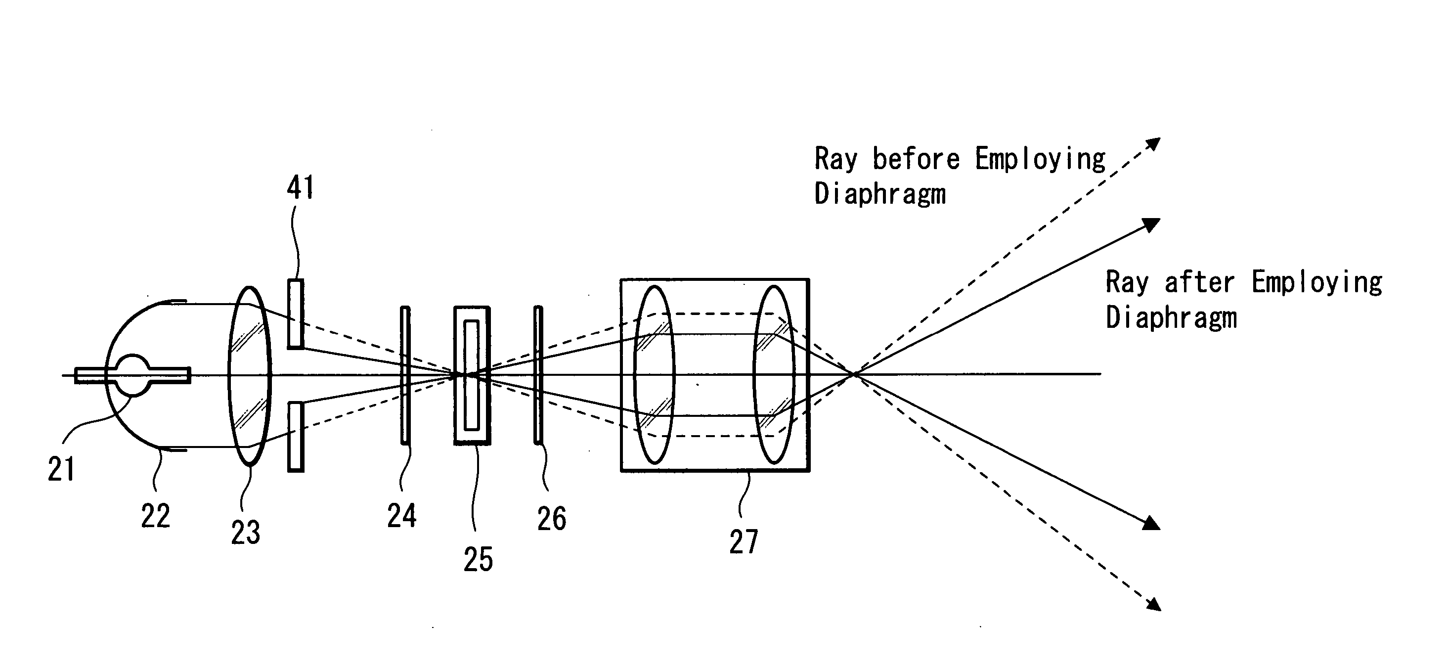
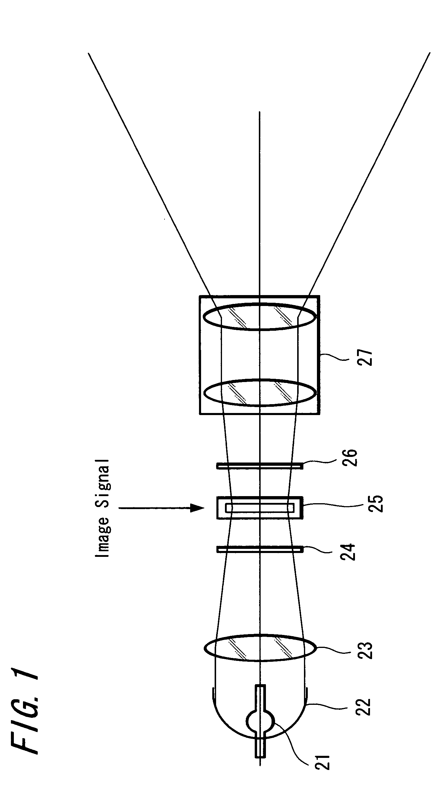
[0062] Hereinafter, this invention is explained in detail using the drawings. FIG. 5 shows an example of the configuration of a liquid crystal projector to which this invention is applied; units common to FIG. 1 are assigned the same symbols. Light is emitted from the light source 21 toward the reflecting mirror 22, Much of the light is collected at the liquid crystal element (liquid crystal panel) 25, which is the spatial light modulation element, by the reflecting mirror 22 and illumination optical system 23.

[0063] A variable diaphragm 1 is positioned in the vicinity of the illumination optical system 23. The variable diaphragm 1 is a mechanical shutter in which the area of the aperture portion can be changed; the area of this aperture portion is increased and decreased by a variable-diaphragm driving unit 2 (a motor which displaces the operating unit of the variable diaphragm 1, and a motor driver or similar which drives the motor).

[0064] Light collected by the reflecting mirro...


PUM


Abstract

A projection-type display device includes: a light source 21; a spatial light modulation element 25 which modulates incident light according to an applied image signal and emits the modulated light; an illumination optical system 23 which condenses light from the light source 21 and illuminates the spatial light modulation element 25; a projection lens 27 which projects the light emitted from the spatial light modulation element 25; shielding unit 1, positioned along the path of light on the side of either the illumination optical system 23 or the projection lens 27 with respect to the spatial light modulation element 25, and which can change the amount of shielding of transmitted light; and image signal correction units 3, 4, 5, and 6 which divide the picture plane of the spatial light modulation element 25 into a plurality of areas, and perform correction on the image signal applied to the spatial light modulation element 25 according to the current shielding amount of the shielding unit 1 for each of the plurality of areas. Accordingly, appropriate uniformity correction is performed even when there is a change in the angular distribution of light emitted from the spatial light modulation element and reaching the screen.

Description

TECHNICAL FIELD [0001] This invention relates to a projection-type display device (projector), and in particular to a projection-type display device having diaphragm-like shielding means to improve contrast. BACKGROUND ART [0002] There has been widespread adoption of projection-type display devices, in which, in conformance to an electrical signal applied to a spatial light modulation element, light incident on the spatial light modulation element is spatially modulated and emitted, and the emitted light is condensed and projected to display an image. Such a projection-type display device conventionally has a lamp and condensing mirror as a light source, and also has an illumination optical system in which light emitted from the light source is condensed and made incident on the spatial light modulation element; and light from the spatial light modulation element is projected onto a screen or similar by a projection lens. [0003] At present, representative spatial light modulation el...

Claims


Application Information

Patent Timeline
IPC IPC(8): G03B21/14G03B21/13G03B37/04H04N5/202H04N5/74H04N9/68H04N9/69H04N9/73
CPCG03B21/13G03B37/04H04N5/202H04N9/73H04N9/68H04N9/69H04N5/7416G02B27/18
Inventor SATO, YOSHIHISA
Owner SONY CORP
Why Eureka
Try Eureka