Optical information device, optical storage medium, optical storage medium inspection device, and optical storage inspection method

a technology of optical information and inspection device, which is applied in the direction of digital signal error detection/correction, instruments, recording signal processing, etc., can solve the problems of power fluctuation that cannot be ignored, recorded signal quality can deteriorate, playback signal quality drops, etc., to reduce the effect of increased jitter, and reduce the effect of jitter

Inactive Publication Date: 2006-01-12
PANASONIC CORP
View PDF10 Cites 14 Cited by
  • Summary
  • Abstract
  • Description
  • Claims
  • Application Information

AI Technical Summary

Benefits of technology

[0045] Yet further preferably, a gain adjustment means for reducing variation in the amplitude of signals input to a demodulation means when reflectivity of the optical storage medium varies is also provided.
[0116] With the configuration of an optical storage medium inspection apparatus according to the present invention described above jitter not including jitter relating to marks and spaces of the shortest recordable length is measured and used to determine whether the optical storage medium is good or defective. More specifically, two threshold values are used to identify the shortest marks. When using a two-layer optical storage medium to which data is recorded with the same recording density on two data recording surfaces, this reduces the effect of increased jitter resulting from marks on the recording layer closer to the optical pickup head being smaller than the desired size, and enables a reliable good / defective determination. The effect of degraded jitter resulting from the shortest marks and spaces can likewise be reduced when applied to an optical disc drive, and data can be reproduced with high reliability from two data recording layers. Data can also be recorded and reproduced with high reliability using an optical storage medium on which jitter from the shortest marks and spaces is worse than jitter from longer marks and spaces.

Problems solved by technology

While data can therefore be correctly recorded with the shortest marks even if the recording power fluctuates somewhat, the effect of power fluctuation cannot be ignored for marks longer than the shortest marks particularly if the recording density increases, and recorded signal quality can deteriorate.
Furthermore, if relative tilt between the optical storage medium and head or defocusing occurs during playback, the playback signal quality drops for signals read from marks longer than the shortest mark, and it may not be possible to correctly reproduce the data.

Method used


Image

  • Optical information device, optical storage medium, optical storage medium inspection device, and optical storage inspection method
  • Optical information device, optical storage medium, optical storage medium inspection device, and optical storage inspection method
  • Optical information device, optical storage medium, optical storage medium inspection device, and optical storage inspection method

Examples


embodiment 1

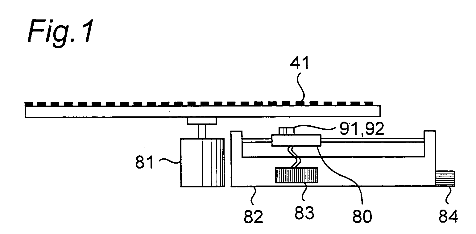
[0146]FIG. 1 shows an example of the configuration of an optical disc drive according to a first embodiment of the present invention. This optical disc drive has an optical pickup head 80, optical disc drive unit 81, optical pickup head drive unit 82, signal processing unit 83, and power supply unit 84. A configuration having a power supply unit 84 is shown in the figure, but a configuration in which a connection terminal (not shown) to an external power supply (not shown) is provided instead of power supply unit 84 and power is supplied by connecting the external power supply and connection terminal could be used. Furthermore, the configuration of the optical pickup head 80 is in no way limited, and the optical pickup head of this embodiment is identical to the conventional configuration shown in FIG. 9.

[0147] The function of each of these components is described next. The optical disc drive unit 81 spins the optical disc 41. The optical pickup head 80 sends a signal corresponding...

embodiment 2

[0185] The configuration of an optical storage medium according to another embodiment of the present invention is shown in FIG. 7. This optical disc 41 has a transparent protective layer 41a and two recording layers 41b, 41c. This optical disc 41 differs from optical storage medium 40 in that data recording layer 41c is a recording layer that can be rewritten multiple times, and data recording layer 41b is a read-only recording layer. Marks are formed in data recording layer 41b by embossing. The shortest marks and spaces are also 2 T. The transmittance of data recording layer 41b is also greater than 50%, and in this preferred embodiment is 80%. Because it is read-only, the transmittance of data recording layer 41b is substantially constant throughout the entire layer. Furthermore, because data recording layer 41b, which is a read-only recording layer, is on the light incidence side of data recording layer 41c, the power of the beam emitted to data recording layer 41c is stable bec...

embodiment 3

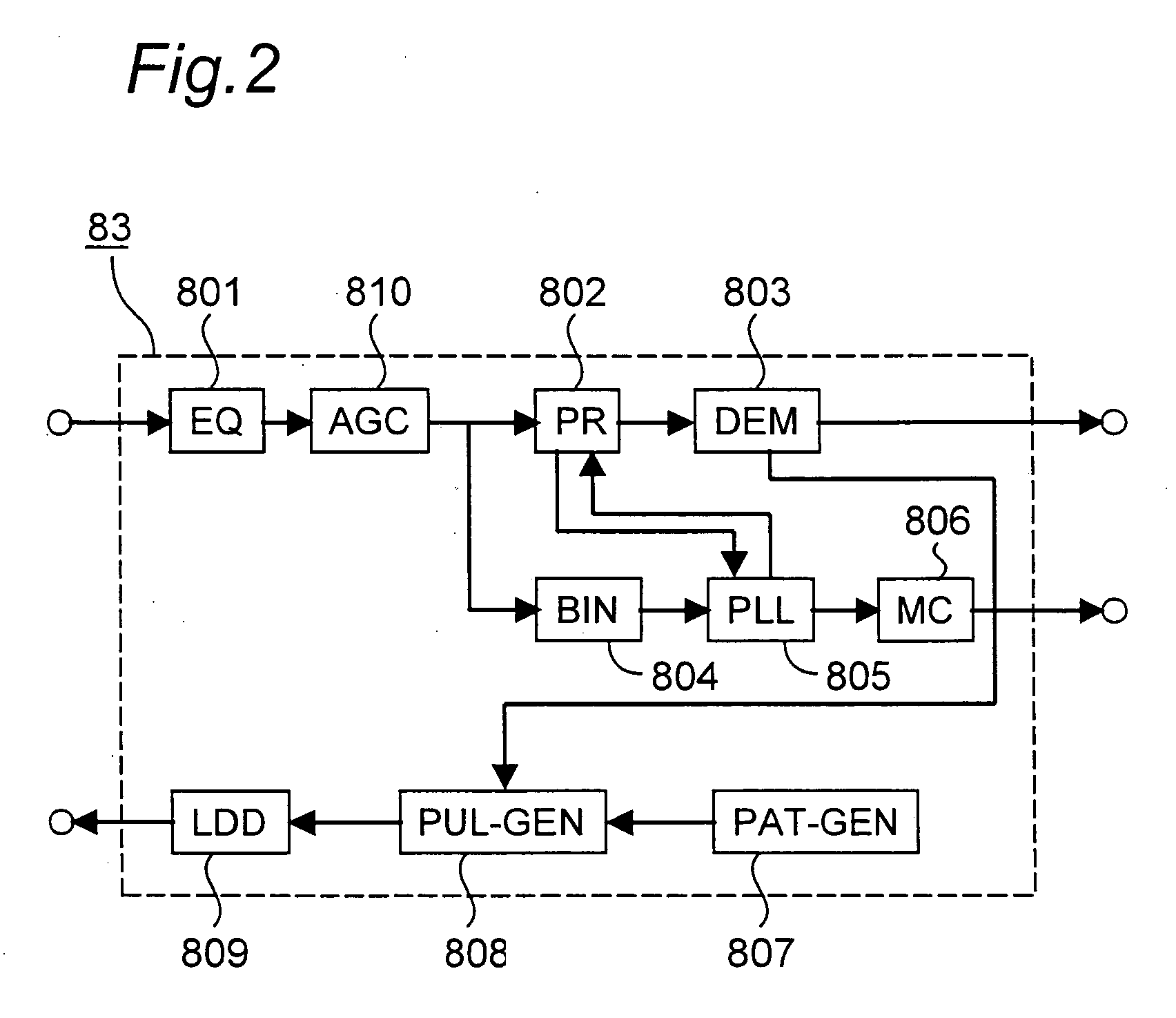
[0191] As another example of an optical disc drive according to the present invention, FIG. 8 shows the configuration of an optical disc drive that generates a TE signal using a phase difference method (also known as a DPD (differential phase detection) method) from an optical storage medium on which 2 T marks and spaces are formed as the shortest marks and spaces.

[0192] An optical storage medium having a recording layer on which embossed marks are formed as described with optical disc 41 according to the second embodiment can be used as the optical storage medium in this embodiment. The optical disc drive can use any type of optical pickup head insofar as the optical pickup head splits the beam in the far field region, detects the reflections with a photodetector, and can output signals enabling phase comparison. This embodiment is described using most common optical pickup head as shown in FIG. 9.

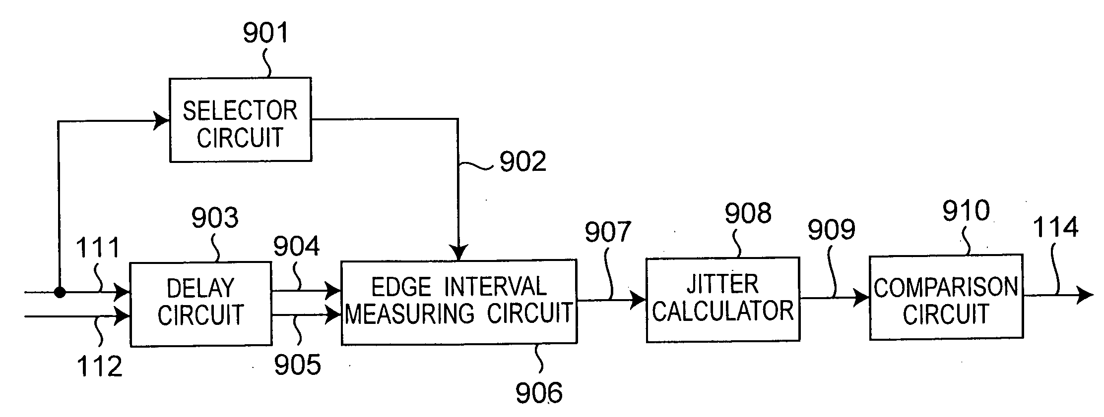
[0193] (a) Signals output from receptors 32a to 32d of photodetector 32 are input t...


PUM

PropertyMeasurementUnit
oscillation wavelength λ1aaaaaaaaaa
focal lengthaaaaaaaaaa

Abstract

This optical disc drive has an optical pickup head that emits a light beam to an optical storage medium, detects the light beam reflected from the optical storage medium, and outputs a signal based on the received reflected light; a jitter measuring unit for measuring jitter in signals output from the optical pickup head; and an evaluation unit for determining from the measured jitter if the optical storage medium is good or defective. The jitter measuring unit measures jitter in a train of 3T or longer marks or spaces from an optical storage medium to which digital information is recorded as a train of marks or spaces of length kT based on a period T and an integer k of two or more.

Description

BACKGROUND OF THE INVENTION [0001] 1. Field of the Invention [0002] The present invention relates to an optical storage medium for recording information using marks and spaces, an optical disc drive for recording, reading, or deleting data on the optical storage medium, an optical storage medium inspection apparatus for determining whether the optical storage medium is good or defective, and an optical storage medium inspection method for determining whether the optical storage medium is good or defective. [0003] 2. Description of the Related Art [0004] High density, high capacity optical storage media known as DVD, or Digital Versatile Disc, have been developed as a practical high density, high capacity storage medium, and are today widely used as a data medium for handling video and other such large amounts of information. Development of two-layer optical storage media capable of recording to two data recording layers has also been reported by various manufacturers as a means of a...

Claims


Application Information

Patent Timeline
Patent Type & Authority Applications(United States)
IPC IPC(8): G11B7/00G01N21/95G01R31/312G01R31/317G11B7/0037G11B20/10G11B20/14
CPCG01N21/9506G11B2220/2537G01R31/31709G11B7/00375G11B7/00456G11B7/00458G11B20/10009G11B20/10027G11B20/10055G11B20/10111G11B20/10296G11B20/10481G11B20/1217G11B20/1426G11B20/225G11B2020/1239G11B2020/1274G11B2020/1298G01R31/312G11B20/14G11B7/004
Inventor KADOWAKI, SHIN-ICHISHOJI, MAMORUNAKAMURA, ATSUSHIISHIDA, TAKASHI
Owner PANASONIC CORP
Why Eureka
Try Eureka