Audio dynamics processing control system

a control system and audio technology, applied in the direction of volume compression/expansion, volume compression/expansion in untuned/low-frequency amplifiers, semiconductor devices, etc., can solve the problem that the most difficult application of noise reduction is the removal, or suppression, and the performance of the control system cannot achieve optimal performance under all conditions, so as to achieve the effect of reducing noise, reducing noise, and reducing nois

Inactive Publication Date: 2006-01-12
WALLER JR JAMES K
View PDF5 Cites 21 Cited by
  • Summary
  • Abstract
  • Description
  • Claims
  • Application Information

AI Technical Summary

Problems solved by technology

One of the most difficult applications for noise reduction is the removal, or suppression of the noise that is present in high gain guitar systems.
While the above disclosed systems and many of the previously available expander noise reduction systems have provided improvements in audio performance, they fall short of achieving optimal performance under all conditions.
As is commonly know in the art, when using a very fast time constant for the control voltage, excessive ripple in the control signal will modulate the VGA of a dynamics processor thereby causing audible distortion, pumping or breathing.
If the input signal contains low frequency components a fast time constant can cause modulation of each cycle of the audio signal, thereby causing undesirable and in some case very audible distortion.
This causes another objectionable side effect in the expander performance.
The result is that when the input signal stops abruptly the prior art expander does not provide any reduction of the input signal until the timing capacitor voltage drops below the preset threshold point.
While the teachings of the 047 patent show one way to improve this problem this design also suffers as a result of having a dead zone in the release response.

Method used


Image

  • Audio dynamics processing control system
  • Audio dynamics processing control system
  • Audio dynamics processing control system

Examples


Embodiment Construction

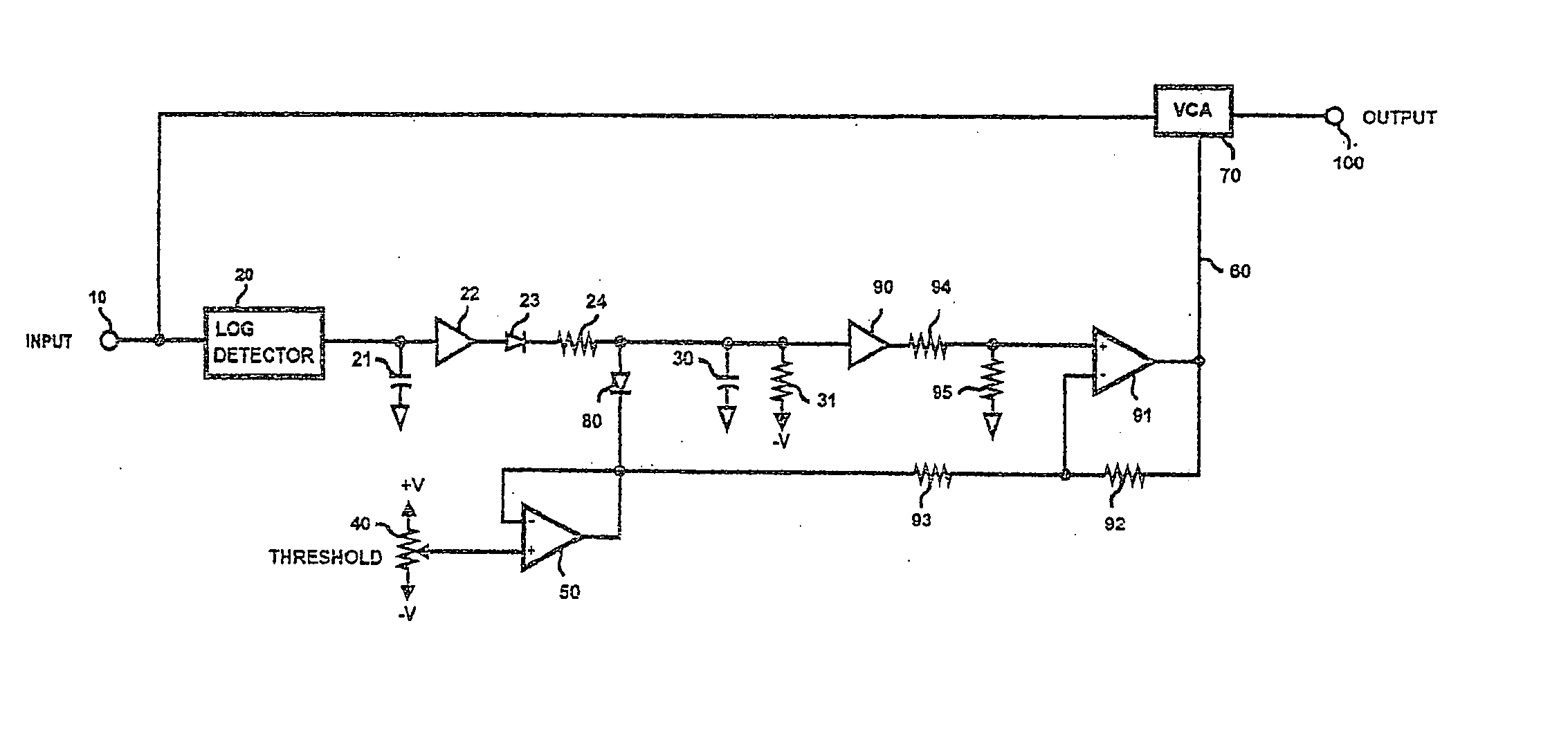
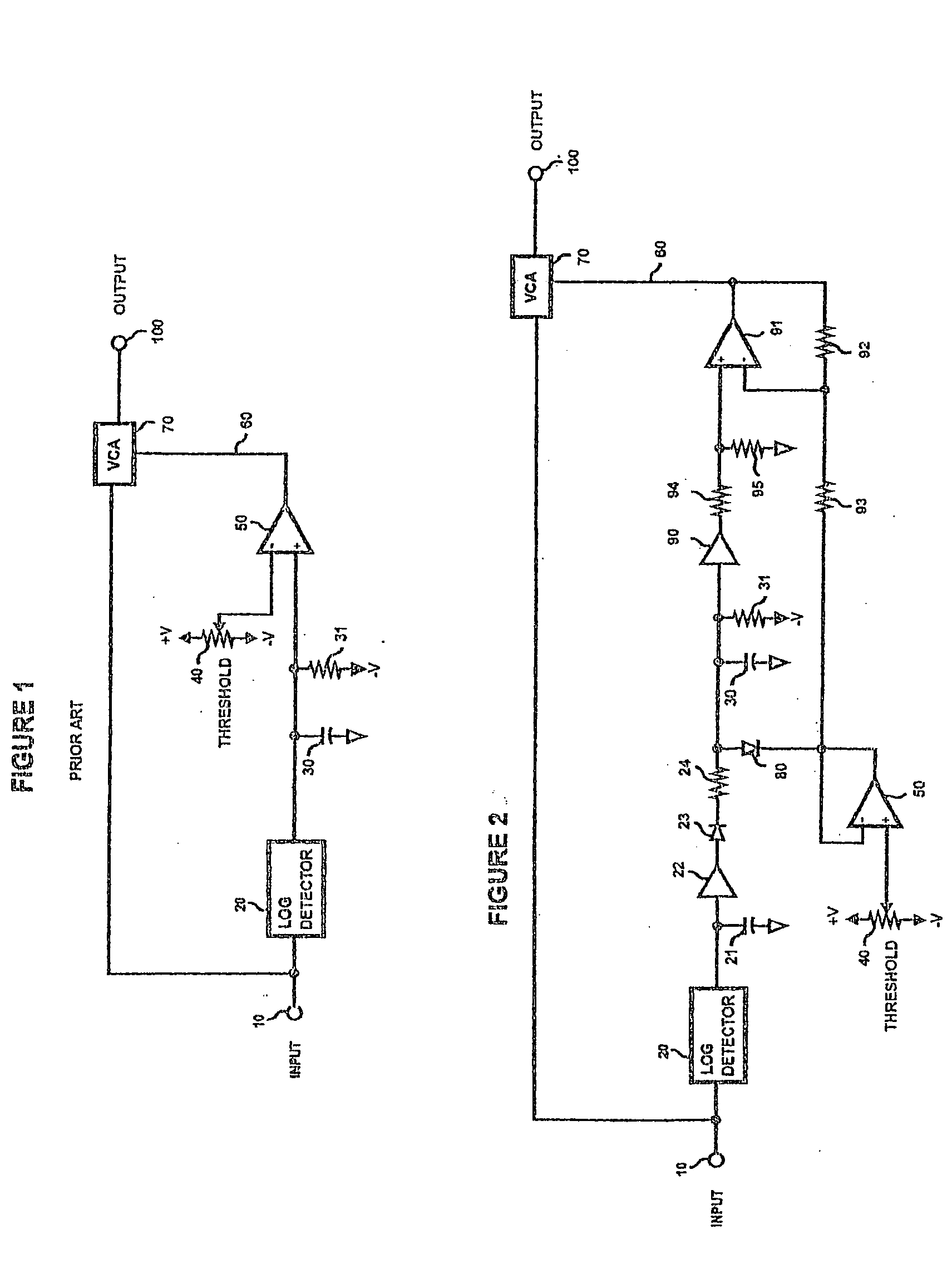
[0012] Referring to FIG. 1, a typical prior art dynamics processor is shown. In the configuration shown, the prior art dynamics processor will operate as a downward expander. The input audio signal is applied to the system input at 10. The input signal at 10 is fed to both the input of a logarithmic based level detector 20 and the input of Voltage Controlled Amplifier (VCA) 70. The output of log detector 20 is filtered and smoothed by capacitor 30. The output of log detector 20 is also connected to timing resistor 31 and the positive input of operational amplifier 50. The negative input of amplifier 50 is connected to variable resistor 40. The skilled artisan will understand that op-amp 50 requires negative feedback for proper operation, this required feedback resistor has been omitted to simplify the prior art drawing. The output of operational amplifier 50 provides a voltage control signal 60 that is applied to the control port of VCA 70. In operation the output of log based level...


PUM


Abstract

An improved dynamics processing control system clamps a level detected control signal at a level equal to a predefined threshold point. In one embodiment, a clamped level detected signal feeds a filter with very slow response characteristics. By comparing the difference between the input and the output of the system a differential control signal generated. The differential control signal is used to provide a continuously variable, program dependant output signal when the input signal drops below a threshold point. In another embodiment of the invention, both the attack and release times of the system are varied in response to a differential control signal.

Description

BACKGROUND OF THE INVENTION [0001] The present invention relates generally to audio dynamics processors such as compressor expanders, limiters, noise reduction systems and more particularly concerns audio processors where the level or amplitude of an audio signal is dynamically altered in response to a generated voltage control signal. In particular the performance of downward expander type noise reduction systems designed for use with musical instruments will greatly benefit from this invention, however all dynamics processors may see improved performance by use of the present invention. All dynamics processors where a VCA (voltage controlled amplifier) or VCF (voltage controlled filter) is used to modify the amplitude or frequency of an audio signal in response to a DC control signal may see the above mentioned improved performance and transparency by use of this improved dynamics processing control system. As will be apparent to the skilled artisan the improvements of the inventi...

Claims


Application Information

Patent Timeline
Patent Type & Authority Applications(United States)
IPC IPC(8): H03G7/00H03G9/00H03G7/06
CPCH03G7/06H03G7/002
Inventor WALLER, JAMES K.
Owner WALLER JR JAMES K
Why Eureka
Try Eureka