Edge router for optical label switched network

a technology of optical label switching and router, applied in data switching networks, multiplex communication, digital transmission, etc., can solve the problems of consuming 400 kw of power, requiring 54 bays of electronics weighing 400 kg, and unable to scale well with increasing the number of wdm wavelengths, etc., and achieves high throughput.

Inactive Publication Date: 2006-01-12
RGT UNIV OF CALIFORNIA
View PDF9 Cites 76 Cited by
  • Summary
  • Abstract
  • Description
  • Claims
  • Application Information

AI Technical Summary

Problems solved by technology

Further increases in speed will be difficult.
Although it is possible to use electronic routers with WDM or DWDM, they do not scale well with increasing number of WDM wavelengths.
If presently available electronic routers are scaled to 10 Tb / s capacity, the router requires 54 bays of electronics weighing 400 kg and consuming 400 kW of power, clearly an uneconomical design.
A WK×WK AWG provides non-blocking switching, but such an AWG having large values of WK is difficult to fabricate.
As described by Yoo, however, a number M of smaller AWGs allows a reduction in the number of routing wavelengths by M2, and the AWGs can operate in parallel with different sets of the WDM wavelengths to provide only limited selection of wavelength, and such a design does not markedly increase the blocking at reasonable traffic loads.
However, there are some problems in integrating it into a complete IP network.
However, we have observed that the optical label switching does not mesh well with electronic routing.
It is expected that a certain number of packets will be lost because of buffer overflow or other reasons.
The system is designed to overcome some loss, but excessive loss becomes unacceptable.
Excessive loss is usually associated with congestion in which a node experiences too much contention and the buffers overflow.
An associated problem arises because there may be different attributes of service for different packets, as indicated by an 8-bit field in the header in this example.
Optical buffers, on the other hand, are not so readily available.
The technology of optical RAM has not been sufficiently developed for use in routers.
Nonetheless, it is fair to say that optical label switching of IP packets is more prone to congestion than is electronic switching, primarily because of the limited depth of delay buffers and because of the need to asynchronously accommodate variable length packets without segmenting them as is possible with electronic routers.
We have determined that such a distribution suffers substantial congestion at optical switching nodes having limited buffering when the optical transmitter load exceeds about 40% of theoretical capacity.
An associated problem involves IP or other networks which have been provisioned with equipment operating at significantly different data rates.

Method used


Image

  • Edge router for optical label switched network
  • Edge router for optical label switched network
  • Edge router for optical label switched network

Examples


Embodiment Construction

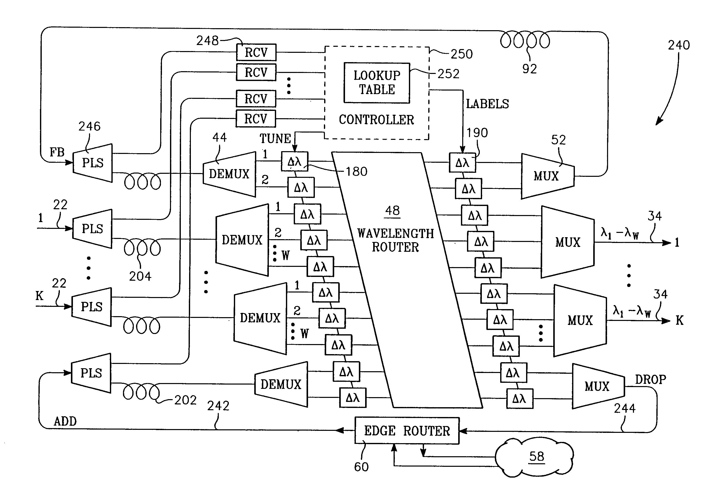
[0047] Although the conventional IP architecture has proven successful in electrical networks and point-to-point fiber networks in which electronic routers are readily and economically available, a more scalable IP network in the future is expected to involve optical label switching (OLS) concentrated in a core network 50 illustrated in FIG. 5, in which optical routers 52 are interconnected by multi-wavelength optical fiber links 54 and can switch packets between the links 54. The optical routers 52 are typically closely associated with edges of the core network 50 and can additionally switch the packets to client networks 58 through edge routers 60. The edge routers 60 are connected to the core network through edge links 56 and to the client networks 58 through client links 62. It is not unusual to have more than one client network 58 or super user 58′ connected to a single edge router 58 at a major entry point to the core network 50. The client networks 58 may be IP networks havin...


PUM


Abstract

An edge router for interfacing an optical label switched core IP network with client networks, which may be electronically switched and operate with different protocol. The core network has a limited number of ports, each with an edge router, which receives packets from one or more associated client networks and queues them according to egress port on the core network and optionally additionally according to attribute of service. When a queue has exceed a maximum packet length or a timeout limit assigned to the queue, the packets including their headers are assembled into a super packet for transmission across the core network in optical form, preferably using optical routers incorporating wavelength conversion of payloads and switching according to an attached label. The edge router at the egress port disassembles the super packet into constituent packets for respective destinations on the client network.

Description

GOVERNMENT INTEREST [0001] The invention was made with Government support under Contract No. F30602-98-C-0218 awarded by the DARPA-NGI. The Government has certain rights in this invention.BACKGROUND OF THE INVENTION [0002] 1. Field of the Invention [0003] The invention relates generally to switches used in communications networks. In particular, it relates to optical packet-based communication networks. [0004] 2. Background Art [0005] An increasing fraction of switched long-distance telecommunications is being performed based on the Internet Protocol (IP). A conventionally conceived Internet-type of communication network 10, as schematically illustrated in FIG. 1, connects multiple terminals 12 through nodes 14 interconnected by bi-directional communications links 16. The terminals 12 can be considered to be ports to other, perhaps different, types of computer networks. The nodes 14 are based on routers which can route sequentially received packets in different directions as the pac...

Claims


Application Information

Patent Timeline
Patent Type & Authority Applications(United States)
IPC IPC(8): H04J14/00H04L12/56H04Q11/00
CPCH04L45/00H04L45/50H04L45/62H04Q2011/0077H04Q11/0071H04Q2011/0064H04Q11/0005
Inventor XUE, FEITAYLOR, JULIEYOO, SUNG-JOO BEN
Owner RGT UNIV OF CALIFORNIA
Why Eureka
Try Eureka