Optical interleaver and filter cell design with enhanced clear aperture

a clear aperture, optical interleaver technology, applied in the direction of multiplex communication, polarising elements, instruments, etc., can solve the problems of limiting factors such as noise and inter-channel interference, and the requirements for optical filters used in any of these applications are very demanding, so as to improve the integrity of optical signals and facilitate packaging

Inactive Publication Date: 2007-02-06
II VI DELAWARE INC
View PDF19 Cites 14 Cited by
  • Summary
  • Abstract
  • Description
  • Claims
  • Application Information

AI Technical Summary

Benefits of technology

[0011]In general, an optical interleaver, filter cell, and component design is provided for use in a wide range of telecommunications, network, and other applications, generally including optical multiplexers / demultiplexers and optical routers. In one example embodiment, an optical interleaver splits and combines optical signals of frequency division multiplexed optical communication channels which are evenly spaced apart in frequency from one another. The optical interleaver includes an optical processing loop which allows multi-stage performance characteristics to be achieved with a single physical filtration stage. Optical processing on the first leg and second legs of the loop improves the integrity of the optical signals by effecting complementary chromatic dispersion on the first and second processing legs. The single physical filtration stage includes a fundamental filter cell and may include one or more harmonic filters. Waveplates may be used to rotate polarization in order to adjust splitting ratios and in order to align interleaver components for more convenient packaging.

Problems solved by technology

The requirements for optical filters used for any of these applications are very demanding.
Various devices, such as multi-stage band and comb splitters, have been proposed to fill these new demanding requirements and none are fully satisfactory.
In either case, noise and inter-channel interference are limiting factors in the handling of increasingly narrow band pass requirements.
Multi-layer thin-film filters can be used to construct optical filters in bulk optics, but they are undesirable because of an increase in the number of layers for narrow channel spacing, precision of manufacture and expense associated with increasingly narrow band pass requirements.
Further, dispersion will become a major issue as channel spacing decreases.
Especially at 50 GHz channel spacing, dispersion of thin film filters is so big that it can not be used for an OC-192 signal (10 Gbit / sec).
Other designs have encountered a variety of practical problems.

Method used


Image

  • Optical interleaver and filter cell design with enhanced clear aperture
  • Optical interleaver and filter cell design with enhanced clear aperture
  • Optical interleaver and filter cell design with enhanced clear aperture

Examples


Embodiment Construction

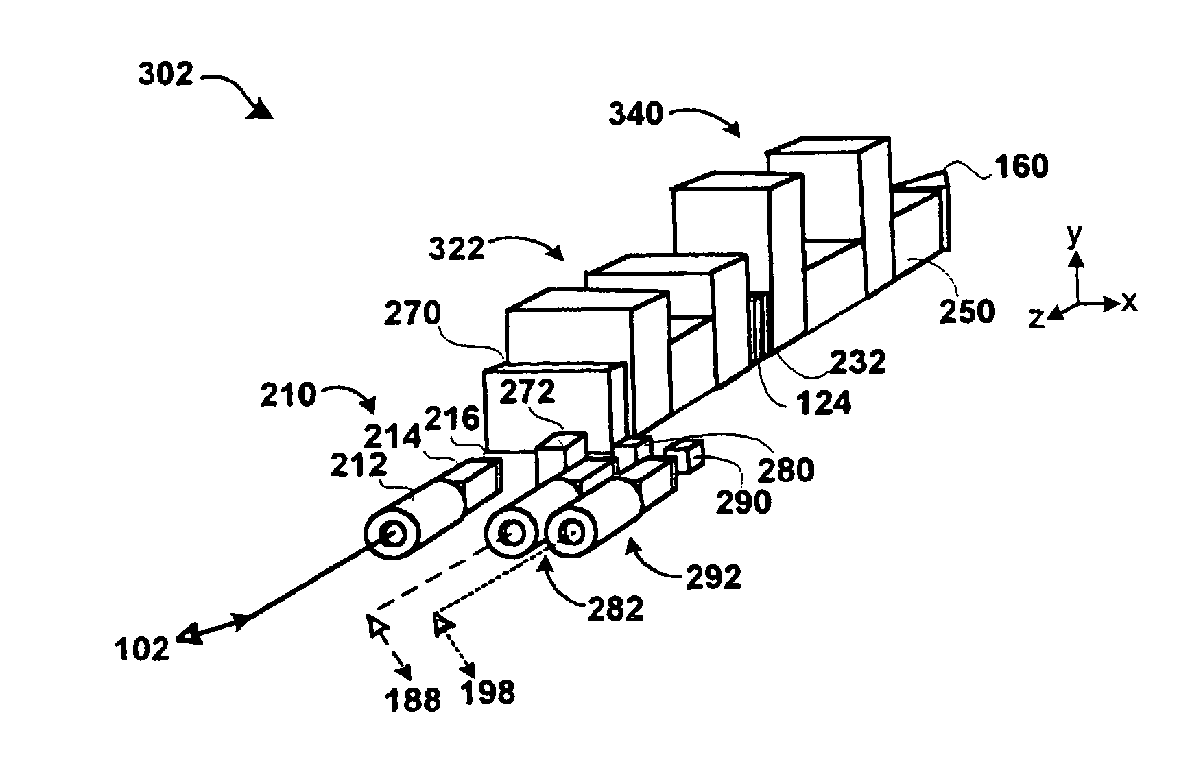
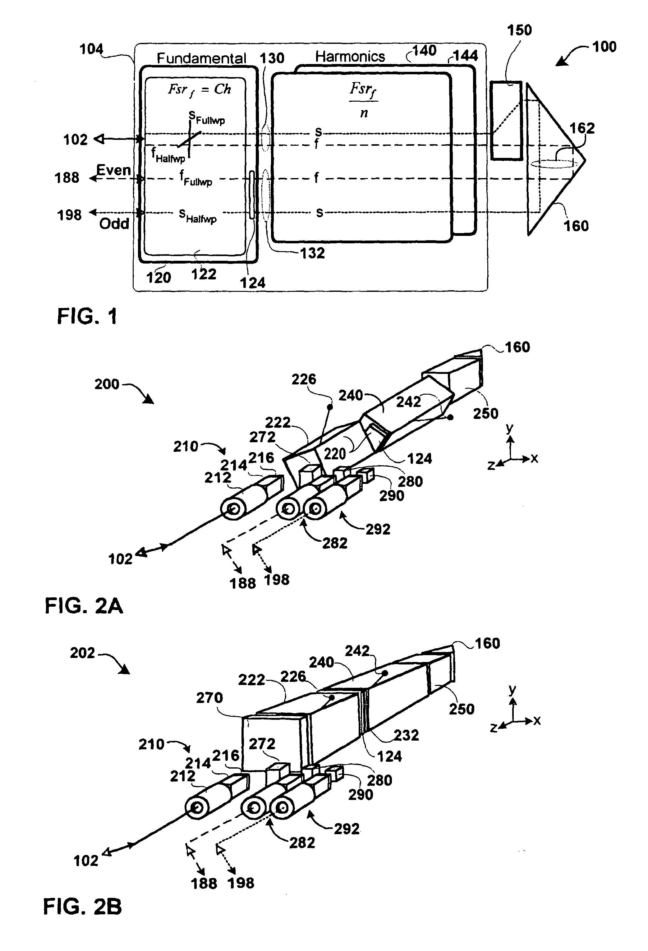
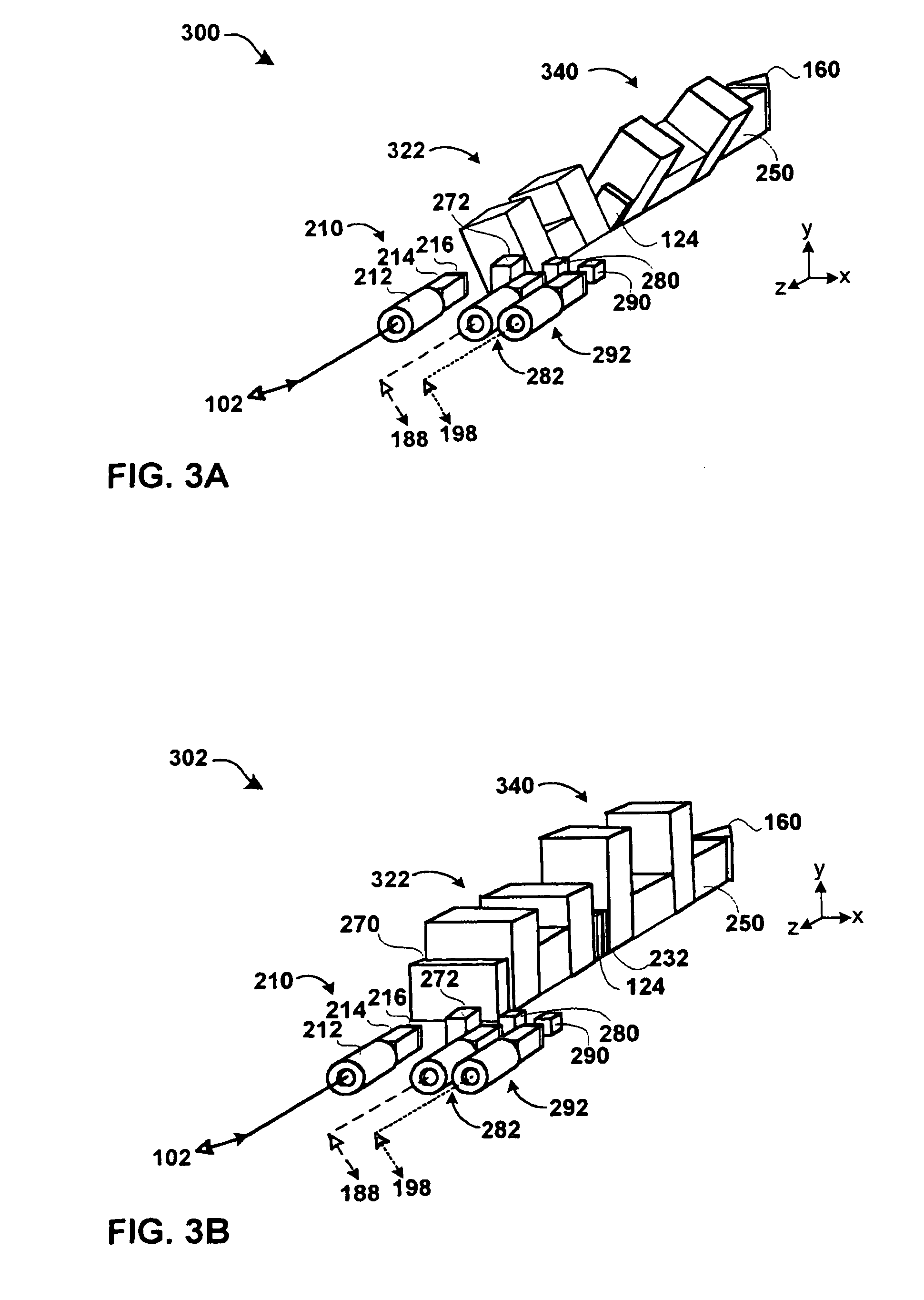
[0054]Various optical interleavers, filter cells, and optical components are disclosed that can be used in a range of telecommunications and other applications including optical multiplexers / demultiplexers and optical routers. An example optical interleaver embodiment includes an optical processing loop which allows multi-stage performance characteristics to be achieved with a single physical filtration stage. Optical processing on the first leg and second leg of the loop improves the integrity of the optical signals by effecting complementary chromatic dispersion on the first and second legs.

[0055]FIG. 1 is a hardware block diagram of an embodiment of an optical interleaver 100 with an optical processing loop 130, 162, 132 formed by a single stage 104 optically coupled to a splitter / combiner 150 and retro reflector 160. As used in this application, optically coupled should be interpreted broadly to encompass optical signal passing between two optical components directly, without an...


PUM


Abstract

An optical interleaver for use in a range of telecommunications applications including optical multiplexers/demultiplexers and optical routers. The optical device includes an optical processing loop which allows multi-stage performance characteristics to be achieved with a single physical filtration stage. Optical processing on the first leg and second legs of the loop is asymmetrical thereby improving the integrity of the optical signals by effecting complementary chromatic dispersion on the first and second legs. A fundamental filter cell within the interleaver filters optical signals propagating on each of the two legs of the optical loop which intersects the fundamental filter cell.

Description

CROSS-REFERENCE TO RELATED APPLICATIONS[0001]This application is a continuation-in-part of application Ser. No. 10 / 170,055 entitled “METHOD AND APPARATUS FOR AN OPTICAL MULTIPLEXER AND DEMULTIPLEXER WITH AN OPTICAL PROCESSING LOOP” filed Jun. 12, 2002 now U.S. Pat. No. 6,850,364, which is incorporated by reference in its entirety.BACKGROUND OF THE INVENTION[0002]1. The Field of the Invention[0003]The present disclosure generally relates to optical interleavers, filters, and components, and more particularly to optical interleavers, filters, and components for optical fiber communication networks.[0004]2. Background and Related Art[0005]The Synchronous Optical Network (SONET) standard defines a hierarchy of multiplexing levels and standard protocols which allow efficient use of the wide bandwidth of fiber optic cable, while providing a means to merge lower level DS0 and DS1 signals into a common medium. Currently optical communication is accomplished by what is known as “wavelength d...

Claims


Application Information

Patent Timeline
Patent Type & Authority Patents(United States)
IPC IPC(8): G02B5/30G02B6/34H04J14/02H04Q11/00
CPCG02B6/272G02B6/29352H04J14/02H04Q11/0005H04Q2011/0075H04Q2011/0015H04Q2011/0016H04Q2011/0026H04Q2011/0009G02B27/126
Inventor DU, TENGDAZHANG, KEVIN DAPENGLUO, XIN
Owner II VI DELAWARE INC
Why Eureka
Try Eureka