Method and apparatus for an optical filter

a technology of optical filters and filters, applied in the field of optical filters, can solve the problems of limiting factors such as noise and inter-channel interference, and the requirements of optical filters used in any of these applications are very demanding, and none are fully satisfactory

Inactive Publication Date: 2002-10-24
II VI DELAWARE INC
View PDF0 Cites 17 Cited by
  • Summary
  • Abstract
  • Description
  • Claims
  • Application Information

AI Technical Summary

Problems solved by technology

The requirements for optical filters used for any of these applications are very demanding.
Various devices, such as multi-stage band and comb splitters, have been proposed to fill these new demanding requirements and none are fully satisfactory.
In either case, noise and inter-channel interference are limiting factors in the handling of increasingly narrow band pass requirements.
Multi-layer thin-film filters can be used to construct optical filters in bulk optics, but they are undesirable because of an increase in the number of layers, precision of manufacture and expense associated with increasingly narrow band pass requirements.
Other designs have encountered a variety of practical problems.

Method used


Image

  • Method and apparatus for an optical filter
  • Method and apparatus for an optical filter
  • Method and apparatus for an optical filter

Examples


Embodiment Construction

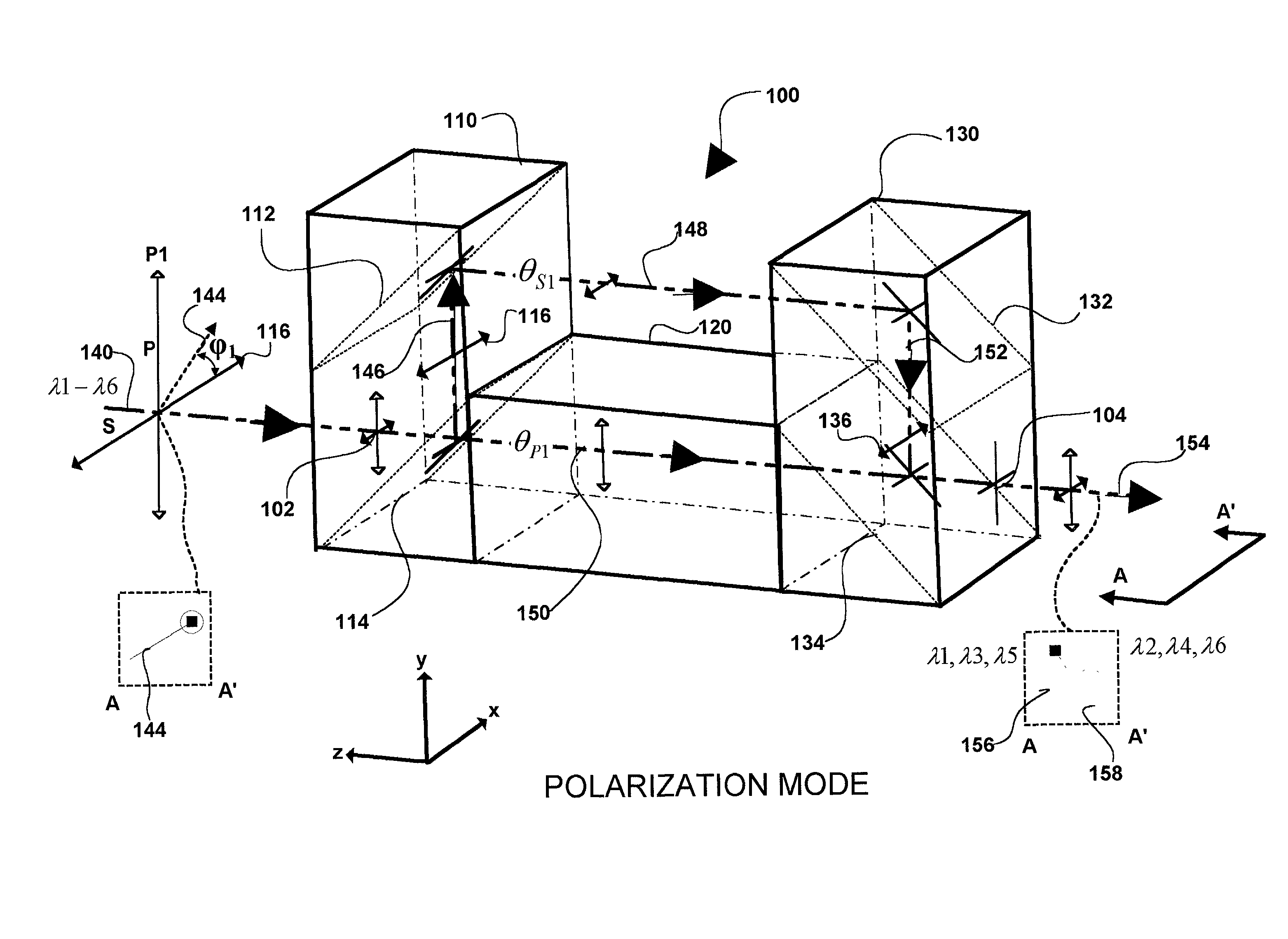
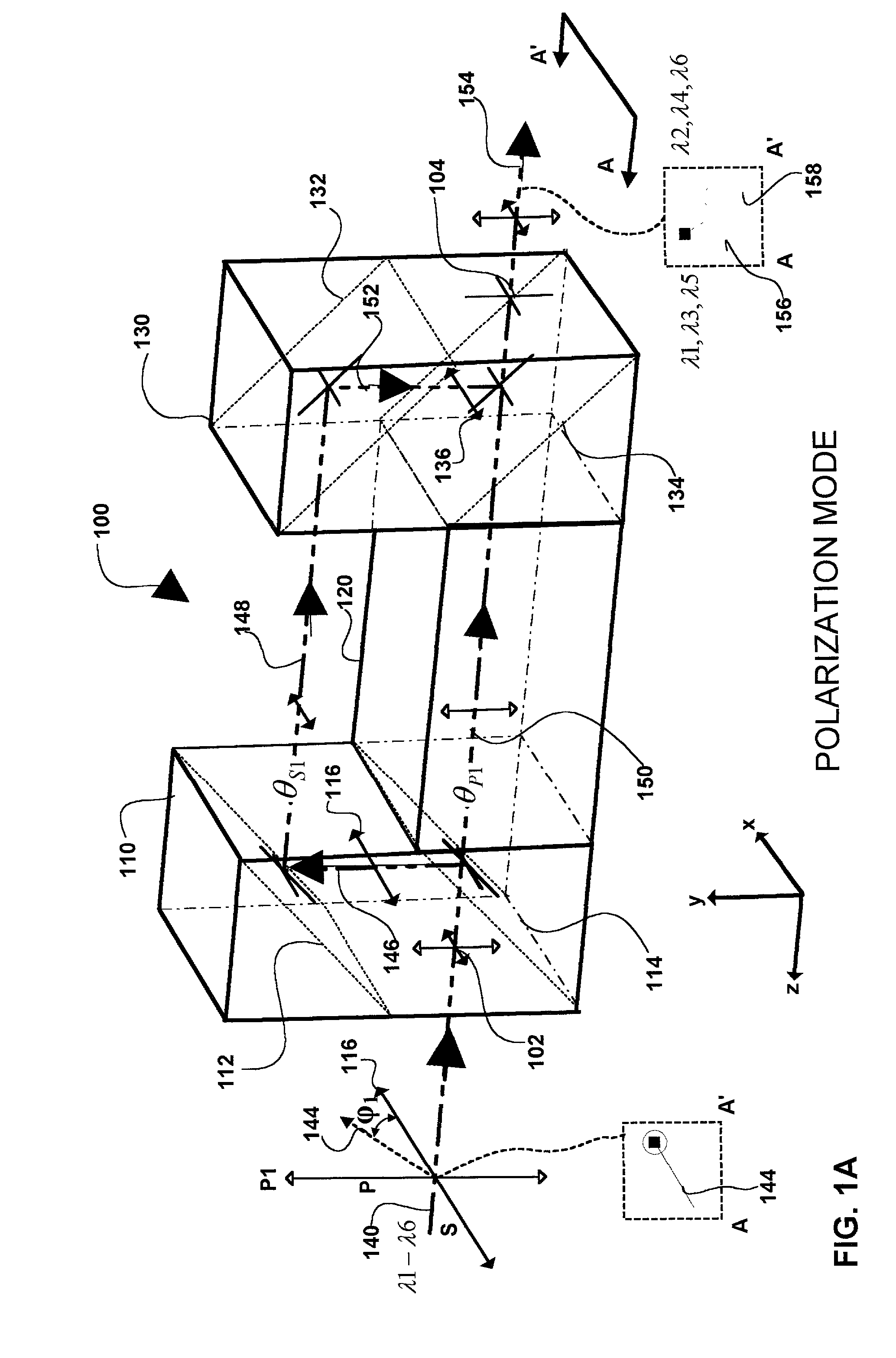
[0026] FIG. 1A is an isometric view of an optical filter cell 100 with couplers employing polarization dependent beam splitting linked by a pair of delay paths 150 and 146,148,152. Each coupler transmits and reflects light depending on the input properties of the light. In the embodiment of the invention shown in FIG. 1A, each coupler is polarization sensitive and includes "P" and "S" polarization axis orthogonal to one another. A first coupler is positioned in the propagation path of incoming polarized light and transmits and reflects components of incoming polarized light aligned with the "P" and "S" polarization axis of the coupler respectively. Light transmitted and reflected by the coupler follows two distinct delay paths, one for transmitted light and the other for reflected light. Where incoming light is orthogonally polarized, the first coupler provides configurable amounts of coupling and cross-coupling of each of the orthogonal polarization vectors of the incoming light wi...


PUM


Abstract

The present invention provides optical filters that can be used in a range of telecommunications applications including optical multiplexers/demultiplexers, optical routers, and optical gain scalers. The optical filter is modular, using two or more couplers with a pair of delay paths between each pair of couplers in a sequence to generate a range of optical filter functions. The desired filter profile/function is obtained by proper selection of the coupling ratio for each coupler and by the length of each pair of delay paths. The couplers may be implemented as polarization or intensity beam splitters positioned along the optical path. Each coupler couples in controllable amounts, one or two inputs with the corresponding pair of delay paths. Where a coupler is implemented as a polarization beam splitter, the coupling is accomplished by input to the coupler of polarized light and by the subsequent separation of orthogonal "P" and "S" components of that light onto corresponding ones of the pair of delay paths. Where coupling is implemented with an intensity beam splitter, the coupling is accomplished by input of light with the percentage of reflection and transmission of the light determining the coupling ratio or percentage of the light input onto corresponding ones of the pair of delay paths. The pair of delay paths includes in an embodiment of the invention, passive thermal stabilization. The passive thermal stabilization of the filter(s) is accomplished by a plurality of optical elements positioned in and defining the optical path length of each member of the pair of paths. These optical elements are designed so that the optical path length difference between the pair of delay paths remains substantially invariant across a range of temperatures.

Description

[0001] 1. Field of Invention[0002] The present invention generally relates to optical filters and more particularly to optical filters for optical fiber communication networks.[0003] 2. Description of the Related Art[0004] The Synchronous Optical Network (SONET) standard defines a hierarchy of multiplexing levels and standard protocols which allow efficient use of the wide bandwidth of fiber optic cable, while providing a means to merge lower level DS0 and DS1 signals into a common medium. Currently optical communication is accomplished by what is known as "wavelength division multiplexing" (WDM), in which separate subscriber / data sessions may be handled concurrently on a single optic fiber by means of modulation of each of those subscriber data streams on different portions, a.k.a. channels, of the light spectrum.[0005] The spacing between channels is constantly being reduced as the resolution and signal separation capabilities of multiplexers and de-multiplexers are improved. Curr...

Claims


Application Information

Patent Timeline
Patent Type & Authority Applications(United States)
IPC IPC(8): G02B6/12G02B6/28G02B6/34
CPCG02B6/12007G02B6/2861G02B6/29302G02B2006/12164G02B6/29398G02B2006/12109G02B2006/12116G02B6/2935
Inventor XIE, PINGWU, SIMON YUANXINAGMAO, YALANWANG, WEIBETTMAN, R. BRADMALUF, NADIM
Owner II VI DELAWARE INC
Why Eureka
Try Eureka