Biomaterial inspection chip

a biomaterial and chip technology, applied in the field of biomaterial detection and/or diagnosis, can solve the problems of increasing manufacturing cost, poor usability, and inability to meet the needs of users, and achieve the effects of reducing the manufacturing cost of the apparatus, improving the usability of the user, and shortening the measuring tim

Inactive Publication Date: 2006-01-12
HITACHI SOFTWARE ENG
View PDF13 Cites 4 Cited by
  • Summary
  • Abstract
  • Description
  • Claims
  • Application Information

AI Technical Summary

Benefits of technology

[0009] According to the present invention, an object thereof is to reduce the manufacturing cost of an apparatus, as well as, improve the usability for a user, through unifying a rinsing liquid and a biomaterial

Problems solved by technology

The biomaterial inspection chip system for DNA, etc., which is made up with the beads, on the surface of which are fixed the probes, however, it has several problems from a viewpoint of designing.
For this reason, it is necessary to change the rinsing liquid or a device for each of the DNA samples, and therefore there is a problem of increasing the m

Method used


Image

  • Biomaterial inspection chip
  • Biomaterial inspection chip
  • Biomaterial inspection chip

Examples


embodiment 1

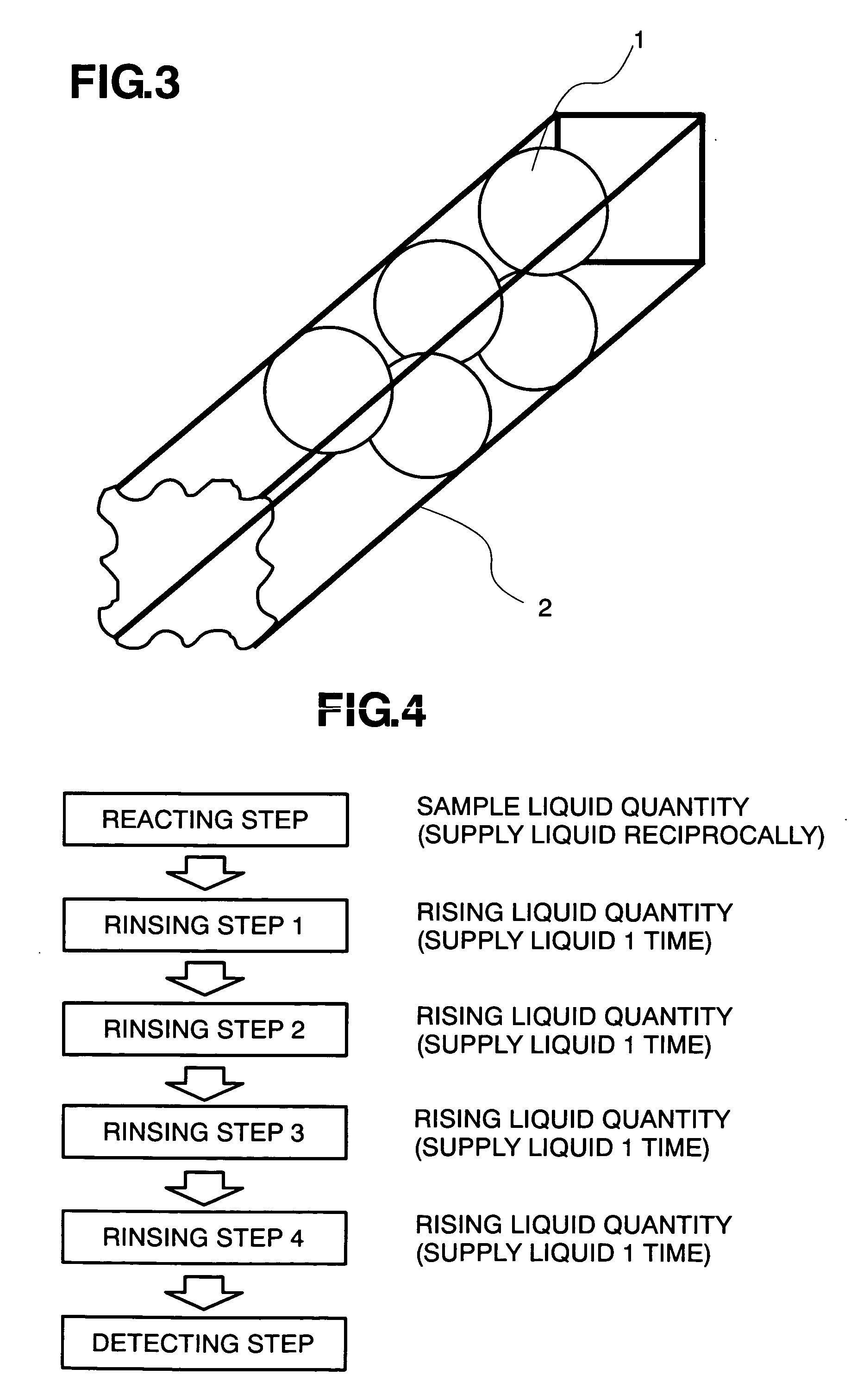
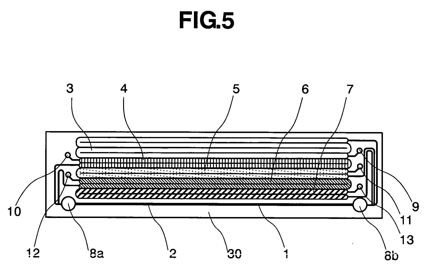
[0044] An inspection chip 30 is manufactured based on an assumption that rinsing or washing must be carried out by four (4) times therein, as is shown in FIG. 4. therewith. FIG. 5 shows the chip 30 holding four (4) kinds of rinsing liquids therein. This chip 30 is for use of the DNA examination or test, and it comprises a reactor flow pass 2, within which beads are provided, four (4) flow passes 4, 5, 6 and 7 for storing four (4) kinds of rinsing liquids therein and a waste fluid flow pass 3 for receiving a part of the used rinsing liquid(s) and the DNA sample liquid after reaction, ports 8a and 8b for carrying the DNA sample liquid, ports 10, 11, 12 and 13 for carrying the rinsing liquids, and a port 9 for carrying the waste liquid. However, since the rinsing liquid differs from depending upon an object of inspection, the number of the flow passes for receiving the rinsing liquids therein is made changeable depending upon the object of inspection. Also, it is possible to add a flow...

embodiment 2

[0054] FIGS. 13(a) and 13(b) show other embodiment of an inspection chip according to the present invention. On the present embodiment, it is also assumed that that rinsing be carried out by four (4) times therein, as is in the first embodiment mentioned above. With the present embodiment, however, the DNA sample and the rinsing liquids held within the inspection chip 30 are measured in the liquid quantity thereof, by means of a liquid surface sensor, and wherein an amount of liquid to be transmitted is controlled with using a liquid surface values measured.

[0055]FIG. 13(a) shows an enlarged DNA inspection chip 30 and a chip cover 31 necessary for sending the test liquid and the rinsing liquids into each of the flow passes. On this chip 30, there are also formed the reactor flow pass 2, within which the beads are aligned, flow passes 4-7 for receiving the four (4) kinds of rinsing liquids therein, the flow pass 14 for holding the DNA sample therein, and the waste liquid flow pass 3...


PUM

PropertyMeasurementUnit
Distanceaaaaaaaaaa

Abstract

Within an inside of a bead chip forming a reactor flow pass therein, rinsing liquid flow passes are also provided in one body. For the purpose of promoting reaction upon a bead array, a turbulence generator or an flow separation stop guide is provided within the reactor flow pass, in which the beads are received. The bead chip is made of a PDMS (Polydimethylsiloxane: (C2H6SiO)n), thereby enabling the reactor flow pass and the rinsing liquid flow passes to be formed freely in the configurations thereof.

Description

[0001] The present application claims priority from Japanese application JP 2004-204537 filed on Jul. 12, 2004, the content of which is hereby incorporated by reference into this application. BACKGROUND OF THE INVENTION [0002] The present invention relates to detection and / or diagnosis of the materials, in particular, relating to an organism, such as, peptide, protein, DNA, RNA, etc., and in particular, it relates to a reaction / detection apparatus of using a probe therein, to be used in analyzing of the materials relating to the organism, such as, DNA and so on. [0003] Due to the fact of completion upon decoding or decipherment about the base sequences of the human genome, a movement comes to be active, in particular, of understanding an organism under the level DNA, thereby to applying into comprehension of the phenomenon of life and also into practical uses of the examination of diseases. For such the purposes, it is important to distinguish a difference in the type of gene and / or...

Claims


Application Information

Patent Timeline
IPC IPC(8): C12Q1/68C12M1/34
CPCB01J2219/00466B01J2219/00468B01J2219/005B01J2219/00576B01J2219/00657B01J2219/00722B01L2300/0883B01L3/5027B01L9/527B01L2200/0647B01L2300/0636B01L2300/0819B01J2219/00725
Inventor INABA, TORUSASAKI, YASUHIKOTOGASHI, SHIGENORIKISHIDA, HIROSHISHIMIZU, TAKASHI
Owner HITACHI SOFTWARE ENG
Why Eureka
Try Eureka