
Push-pull type ventilation hood

Inactive Publication Date: 2006-01-12
INST OCCUPATIONAL SAFETY & HEALTH COUNCIL LABOR AFFAIRS EXECUTIVE YUAN
View PDF6 Cites 19 Cited by
  • Summary
  • Abstract
  • Description
  • Claims
  • Application Information

AI Technical Summary

Benefits of technology

[0009] The main purpose of the present invention relates to a push-pull type ventilation hood. More particularly, the present invention relates to a design of a push-pull hood for pulling and exhausting contaminant flow. By the present invention, the dispersion of the contaminant in the laborers' work environment can be reduced; the safety and health of the industrial environments can be improved; the probability of occupational diseases among laborers can be reduced; and, the productivity of the country can also be improved at the same time.
[0010] Another purpose of the present invention is to improve the efficiency of the exhausting and capturing; to reduce the power consumption in the pulling process; to provide a control on the dispersing contaminant in an economical and effective way for the business unit; and, to further provide an improvement on guarding and controlling the work environment.
[0012] The fourth purpose of the present invention is to provide a specific design process together with setting a flange to make a push-pull hood which consumes less power and is highly efficient and produces low pollution.

Problems solved by technology

From a dispersing contaminant source, such as an open-surface tank for electroplating or acid-etching, a great amount of the contaminant will be released from the liquid surface quite fast together with the reaction temperature inside the tank to make the environment around seriously affected and the flow field around quite obviously crowded so that the laborers' health and the industrial operation safety will be directly threatened.
But, because the flow is crooked owing to the dispersion velocity and the tank surface width is too wide, the pulling capacity of a general partial-exhausting hood is not able to be effectively controlled.
Because the push flow source is a dispersing source too, the flow field around will be crowded and dispersed.
Therefore, the suggested values are only suitable for contaminants with lower dispersion velocity to make the operation points fall in the transition mode and the encapsulation mode.
Yet, when the dispersion velocity of the contaminants is getting higher, the operation point will fall in the dispersion mode and the transition mode; and, because the push velocity would be required to be higher, the power will be consumed more.

Method used


Image

  • Push-pull type ventilation hood
  • Push-pull type ventilation hood
  • Push-pull type ventilation hood

Examples


Embodiment Construction

[0023] The following descriptions of the preferred embodiment are provided to understand the features and the structures of the present invention.

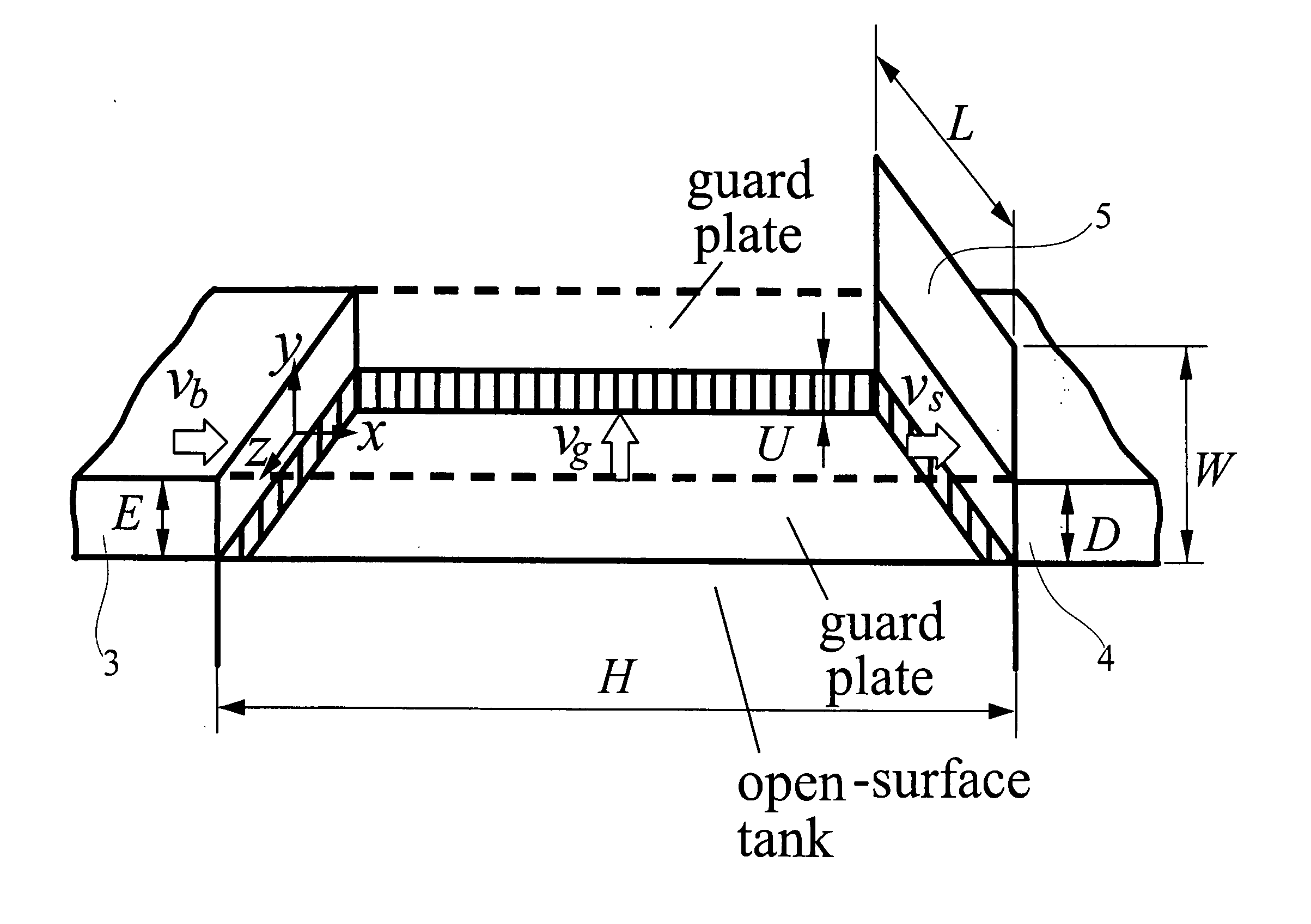
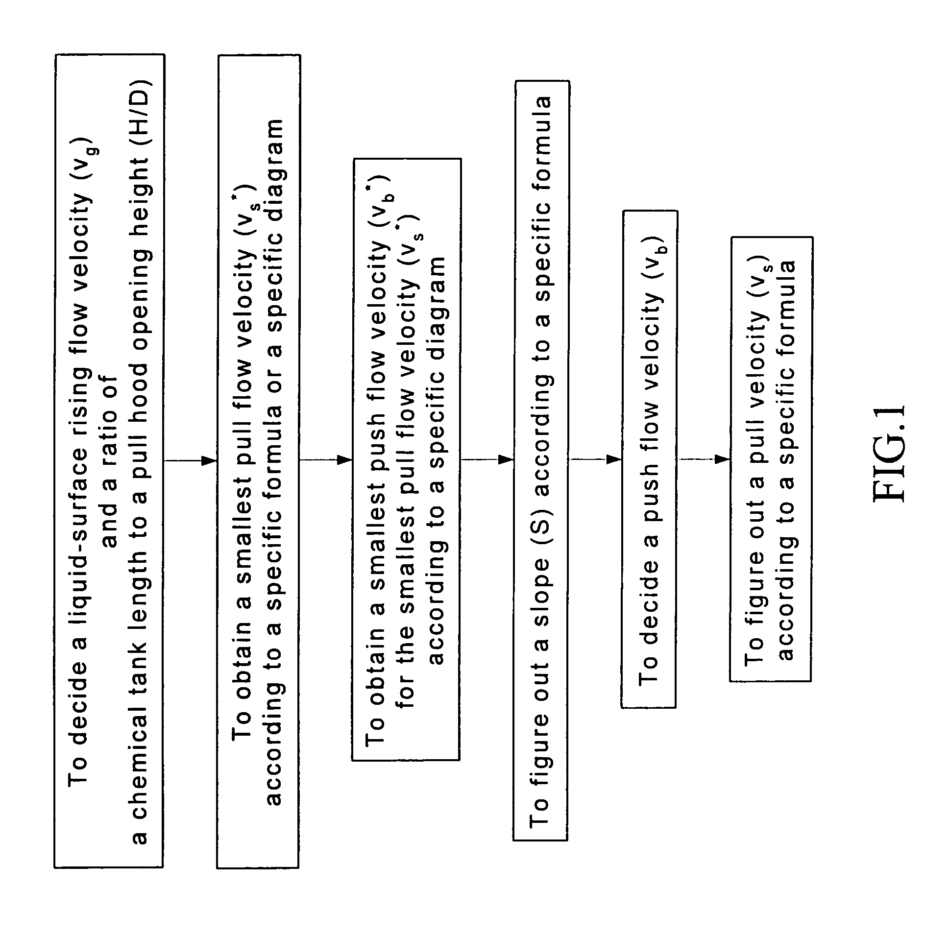
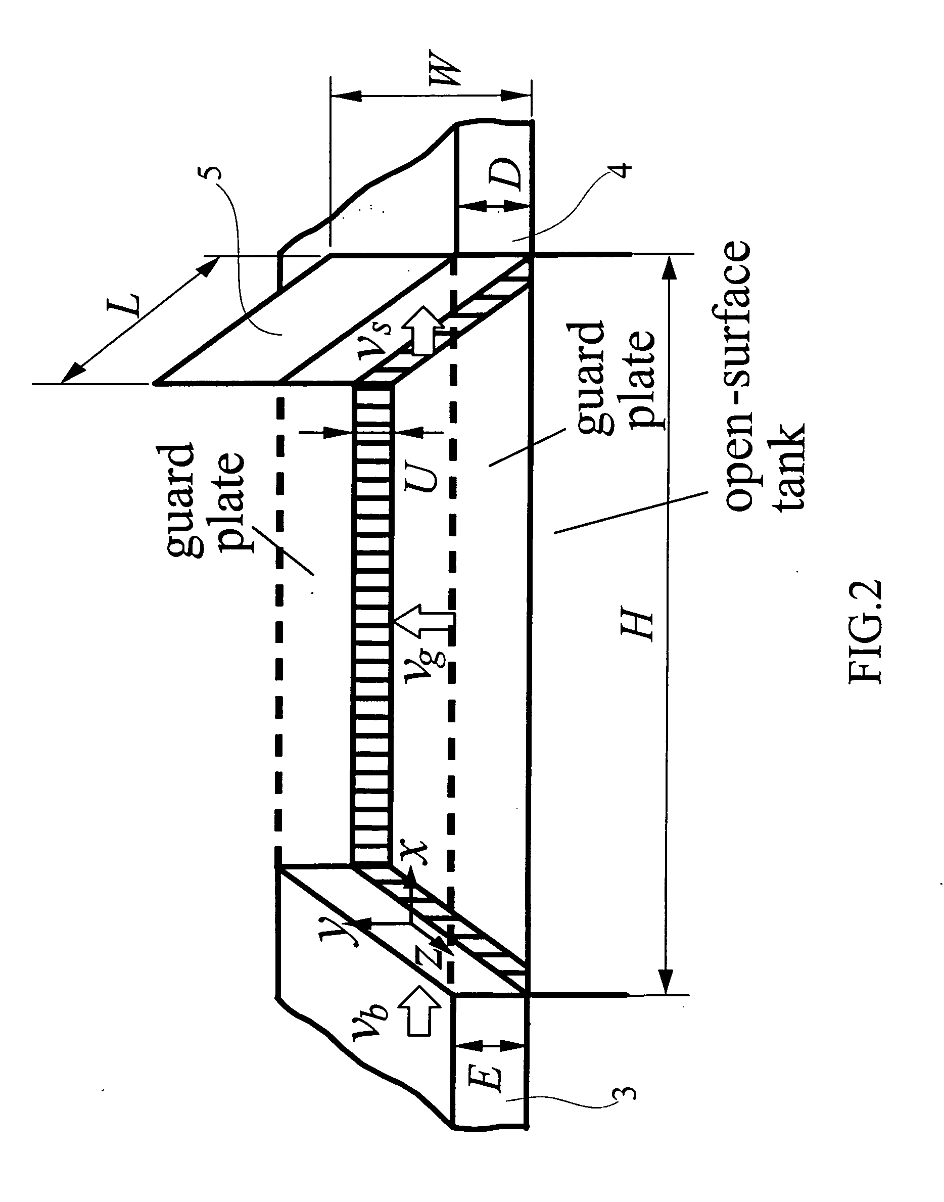
[0024] From the experiment results of the preferred embodiment according to the present invention, it can be found that many parameters would affect the design of a push-pull hood. These parameters include the parameters concerning the flow field velocity, such as the average flow velocity per unit area of the push hood opening (vb), the average flow velocity per unit area of the pull hood opening (vs) and the rising velocity of simulated chemical vapor (vg); and the parameters concerning the geometrical design, such as the chemical tank length (H), the pull hood opening height (D) and the push hood opening height (E); and so on. Although there are too many experimental parameters to be controlled, based on the experiment results according to the present invention, a simple and effective design process is provided with regard to the impor...


PUM


Abstract

The present invention is a push-pull ventilation hood having a push device to obtain a push air flow and a pull device to exhaust contaminant flow with an exhaust opening and the two devices properly coordinated with each other, wherein, when the push flow flows through a contaminant source, a contaminated flow of the push flow is exhausted through the exhaust opening. Based on the design process according to the present invention, a push-pull hood with the highest efficiency of push velocity can be designed and the push-pull hood can economically and effectively control the contaminant source.

Description

FIELD OF THE INVENTION [0001] The present invention relates to a push-pull type ventilation hood. More particularly, the present invention relates to that, by a specific design process and an improvement in structure design, the ability of a push-pull hood on capturing the contaminant flow is improved. The present invention uses smoked-flow visualization to find out four characteristic flow regimes for different types of push flow and pull flow, wherein the four characteristic flow regimes are regimes of dispersion, transition, encapsulation and strong suction; and wherein the contaminant can be safely captured in the modes of encapsulation and strong suction. By the specific design process, the present invention find out the most effective push velocity and pull velocity together with the design of a flange to make a push-pull hood capable of economically and effectively controlling the contaminant source. DESCRIPTION OF THE RELATED ARTS [0002] The design of ventilation has progres...

Claims


Application Information

Patent Timeline
IPC IPC(8): B08B15/02
CPCB08B2215/003B08B15/007
Inventor HUANG, RONG FUNGCHEN, YU-KANGSHIH, TUNG-SHENGCHANG, CHENG-PINGYEH, WEN-YUCHEN, CHUN-WANLIN, SHIN YIJAN, SHUN-YUAN
Owner INST OCCUPATIONAL SAFETY & HEALTH COUNCIL LABOR AFFAIRS EXECUTIVE YUAN
Learn More