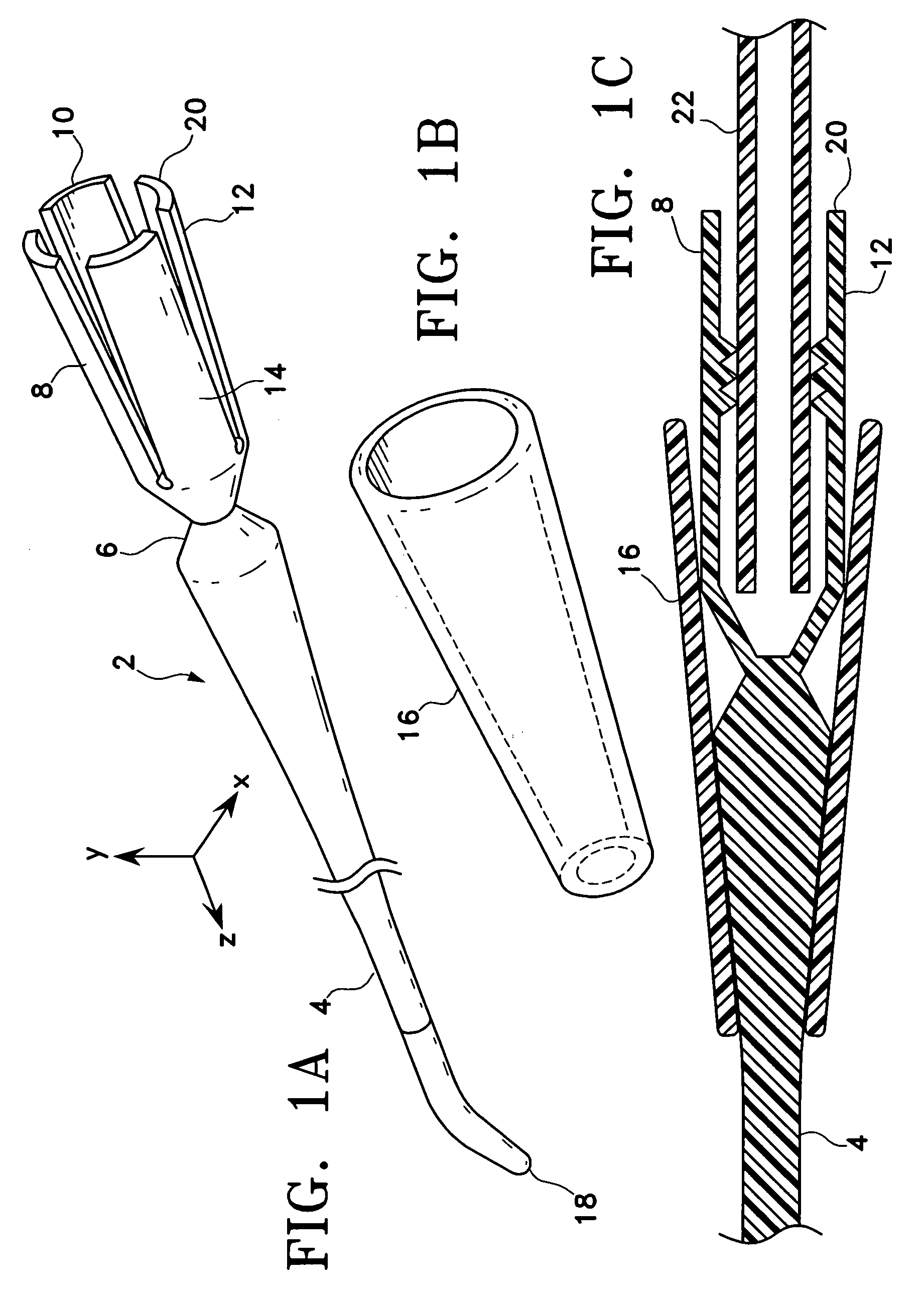
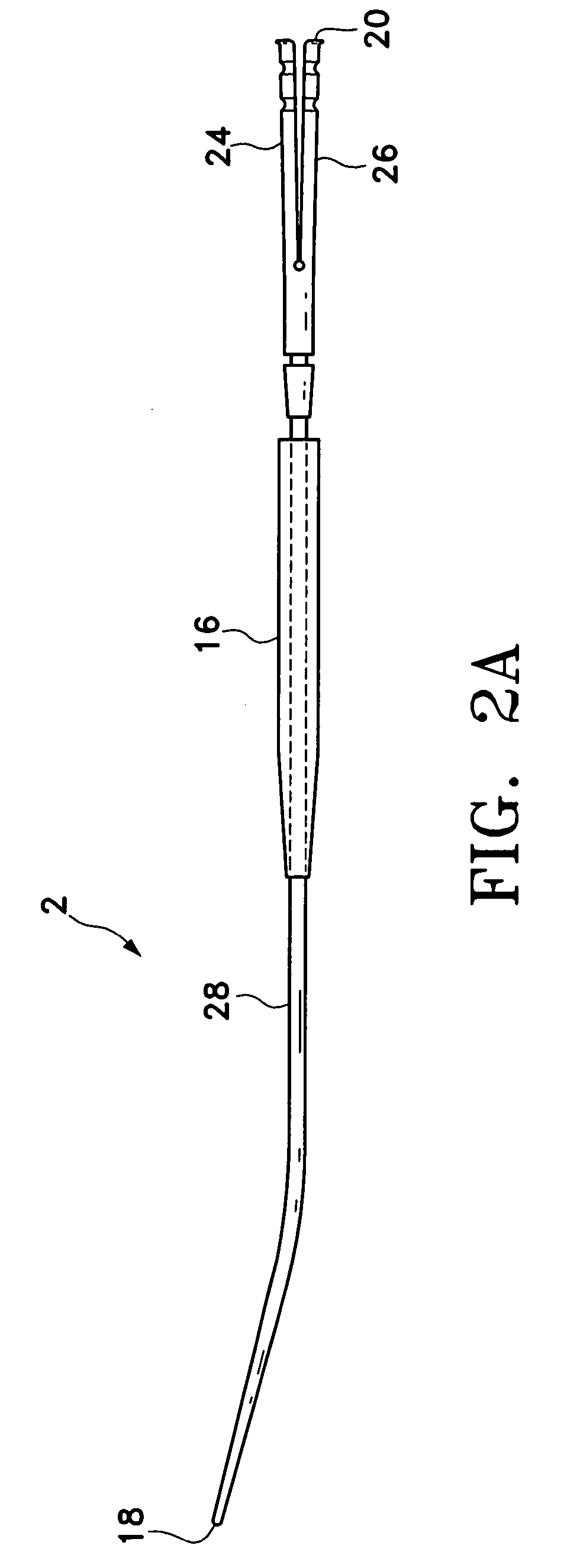
Tunneler with gripping mechanisms

Inactive Publication Date: 2006-01-12
CR BARD INC
View PDF36 Cites 89 Cited by
  • Summary
  • Abstract
  • Description
  • Claims
  • Application Information

AI Technical Summary

Benefits of technology

[0010] Accordingly, described herein is a tunneling device having a gripping mechanism to secure the catheter by holding onto the body of the catheter (i.e., a distal portion or a proximal portion of the catheter) rather than just the distal tip or proximal end of the catheter. This improved tunneler may prevent damage to the catheter that can be experienced using previous designs that require insertion of a barb(s) or other large protrusion(s) into the distal or proximal lumen of the catheter. In one variation, the tunneling device comprises three parts: a tunneler, a collet and a sheath. The tunneler comprises an elongated body with a tapered distal end for insertion into bodily tissues. The tunneler may be fabricated from surgical steel or other metallic and/or polymeric materials with proper strength to support forces needed to separate tissues such that the tunneler may pass through. The collet may comprise a compression sleeve having a plurality of fingers that are separated and flare outward from a unitary distal end away from the central axis of the device. The collet may be configured for positioning at the proximal end of the tunneler. The compression sleeve may be fabricated from metal, plastic or other polymeric material. The sheath may comprise an oversleeve that can be slid over the tunneler from its distal end toward its proximal end to force the fingers on the collet to compress inward toward the central axis of the tunneler.
[0011] To assemble, the compression sleeve is slid o

Problems solved by technology

However, a common problem associated with implanted catheters is the increased risk of infection due to the establishment of this artificial path into the patient's body.
The risk of infection increases the longer the catheter remains implanted.
One of the disadvantages of the current tunneling devices is that the tunneler must be differently sized for differently sized lumens, as well as the fact that attachment and removal of the barbed end from the lumen of the catheter often results in damage to the lumen and t

Method used


Image

  • Tunneler with gripping mechanisms
  • Tunneler with gripping mechanisms
  • Tunneler with gripping mechanisms

Examples


Embodiment Construction

[0034] The following detailed description should be read with reference to the drawings, in which like elements in different drawings are identically numbered. The drawings, which are not necessarily to scale, depict selected preferred embodiments and are not intended to limit the scope of the invention. The detailed description illustrates by way of example, not by way of limitation, the principles of the invention. This description will clearly enable one skilled in the art to make and use the invention, and describes several embodiments, adaptations, variations, alternatives and uses of the invention, including what is presently believed to be the best mode of carrying out the invention.

[0035] Before describing the present invention, it is to be understood that unless otherwise indicated this invention need not be limited to applications in human. As one of ordinary skill in the art would appreciate, variations of the invention may be applied to other mammals as well. Moreover, ...


PUM


Abstract

A tissue tunneling device having a gripping mechanism for holding onto the body of the catheter. In one variation, the tissue tunneling device includes an elongate tunneler with a collet attached to the proximal end of the tunneler, and an oversleeve for providing compression to the collet to secure a distal or proximal portion of the catheter within the proximal end of the tunneling device. Internal ribs or surface profiles may be provided on an inner surface of the collet to prevent the catheter from moving when the collet is compressed onto the body of the catheter. The oversleeve may be configured such that over-sliding in the proximal direction is prevented. The collet may further be configured to receive the tips of a split-tip dialysis catheter.

Description

CROSS-REFERENCE TO RELATED APPLICATIONS [0001] Not applicable. STATEMENT REGARDING FEDERALLY SPONSORED RESEARCH OR DEVELOPMENT [0002] Not applicable. REFERENCE TO A COMPACT DISK APPENDIX [0003] Not applicable. BACKGROUND OF THE INVENTION [0004] In various medical applications an implanted catheter is needed to access a patient's circulatory system. The implanted catheter may be utilized for delivery of medication / fluids or retrieval / sampling of blood. For example, it may be desirable to establish a central line (i.e., access to a large vein) for infusion of medications, chemotherapy drugs, antibiotics, anti-nausea medications, blood products, nutrients or fluids. Implanted catheters are also used in dialysis, apheresis, and other applications requiring diversion of a part of the blood flow in the circulatory system for processing or filtering. However, a common problem associated with implanted catheters is the increased risk of infection due to the establishment of this artificial ...

Claims


Application Information

Patent Timeline
IPC IPC(8): A61F11/00
CPCA61B17/3415A61M25/0194A61B2017/320044A61B2017/00477
Inventor ROME, GUYMARTIN, TIMOTHY L.FARNWORTH, CHARLES L.
Owner CR BARD INC
Why Eureka
Try Eureka