Method and apparatus for accessing a building system model

a building system and model technology, applied in the field of building automation systems, can solve the problems of limited ability to use such data, limited ability of most building systems to associate sensor values with other building systems or general building attributes, etc., and achieve the effect of facilitating a large set of extended services

Inactive Publication Date: 2006-01-12
SIEMENS IND INC
View PDF34 Cites 61 Cited by
  • Summary
  • Abstract
  • Description
  • Claims
  • Application Information

AI Technical Summary

Benefits of technology

[0008] The present invention provides an improved building system model and method for accessing the same for use in software applications. The model is a data mode that links information regarding building topology and building automation devices, among other things. The model facilitates a large set of extended services.

Problems solved by technology

However, most building systems have limited ability to associate sensor values with other building system or general building attributes.
While systems with such graphics provide at least some integrated visible representation of portions of the building automation system, the ability to use such data is limited.

Method used


Image

  • Method and apparatus for accessing a building system model
  • Method and apparatus for accessing a building system model
  • Method and apparatus for accessing a building system model

Examples


Embodiment Construction

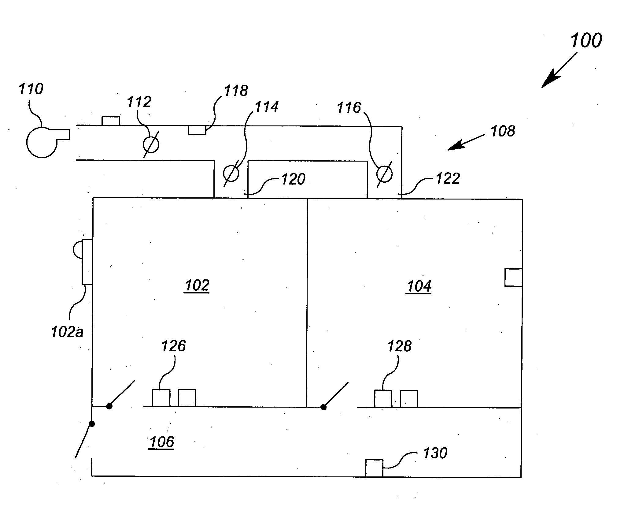
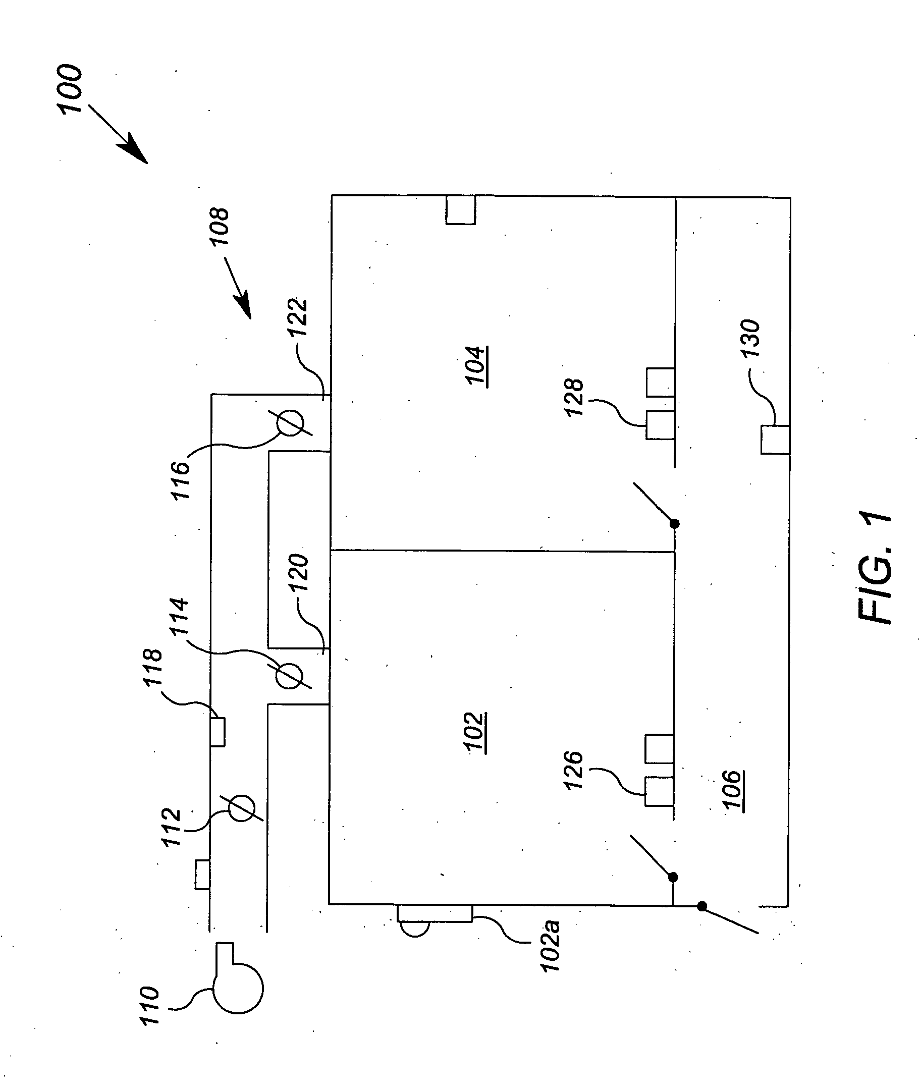
[0029]FIG. 1 shows a top view of a building zone 100 that includes a number of building automation devices that form a portion of the heating, ventilation and air conditioning (“HVAC”) for the building system. The building zone 100 includes a first room space 102, a first window 102a, a second room space 104, a hall space 106 and mechanical space 108. The mechanical space 108 is illustrated as being adjacent to the room spaces 102 and 104 for clarity of exposition, but in actuality would also typically extend over the top of the first room space 102, the second room space 104, and the hall space 106.

[0030] The portion of the HVAC system shown in FIG. 1 includes a blower 110, a shaft damper 112, a first room damper 114, a second room damper 116, a flow sensor 118, a first room inlet 120, a second room inlet 122, a shaft branch 124, a first temperature sensor 126, a second temperature sensor 128, and a space temperature adjuster 130. Also shown in FIG. 1 is a security sensor 132 that...


PUM


Abstract

A software interface is disclosed for a model of a building system stored in a memory, wherein the model comprises a plurality of building space objects. The software interface comprises: (a) logic for receiving a call comprising a function identifier and at least one object identifier, the function identifier representative of a function applicable to a plurality of object types; and (b) logic for employing the function identifier and the at least one object to call a software function in a function library, the software function corresponding to the function applicable to the object type that corresponds to the at least one object.

Description

[0001] This application claims the benefit of U.S. Provisional Patent Application Ser. Nos. 60 / 583,519, 60 / 583,572, and 60 / 583,585, each filed Jun. 28, 2004, all of which are incorporated herein by reference.FIELD OF THE INVENTION [0002] The present invention relates generally to building automation systems, and more particularly, to methods and apparatus for representing and / or storing building automation system data. BACKGROUND OF THE INVENTION [0003] Building automation systems are comprehensive and distributed control and data collection systems for a variety of building automation functions. Such functions may include comfort systems (also known as heating, ventilation and air condition or HVAC systems), security systems, fire safety systems, as well as others. Building automation systems include various end points from which data is collected. Examples of such end points include temperature sensors, smoke sensors, and light sensors. Building automation systems further include ...

Claims


Application Information

Patent Timeline
Patent Type & Authority Applications(United States)
IPC IPC(8): G05B11/01G01M1/38G05B13/00G05B15/00G05B21/00G05D23/00G05B15/02G06F3/00G06F9/00G06F17/00G06Q10/00
CPCG05B15/02G06Q10/10Y10S707/99948Y10S707/99945G06Q50/08
Inventor IMHOF, RAPHAELRULE, THOMASAHMED, OSMANSONGKAKUL, PORNSAKPHOENIX, GEORGE
Owner SIEMENS IND INC
Why Eureka
Try Eureka