Manufacturing method of piezoelectric vibrator unit, manufacturing method of liquid jet head, piezoelectric vibrator unit, and liquid jet head

a piezoelectric vibrator and manufacturing method technology, applied in the direction of mechanical vibration separation, instruments, etc., can solve the problems of lowering production efficiency, and affecting the production efficiency of piezoelectric vibrators

Inactive Publication Date: 2006-01-19
SEIKO EPSON CORP
View PDF14 Cites 3 Cited by
  • Summary
  • Abstract
  • Description
  • Claims
  • Application Information

AI Technical Summary

Benefits of technology

[0020] a displacement amount adjustment step of setting a treatment condition for at least one of the piezoelectric vibrators based on a result of measurement by the displacement amount measurement step, and subjecting the at least one of the piezoelectric vibrators to a displacement amount adjustment based on the thus set treatment condition, thereby making the displacement amounts of the piezoelectric vibrators uniform.
[0062] an ejection characteristic adjustment step of setting a treatment condition for at least one of the piezoelectric vibrators based on a result of measurement by the ejection characteristic measurement step, and subjecting the at least one piezoelectric vibrator to a displacement amount adjustment based on the thus set treatment condition, thereby making the liquid ejection characteristic associated with the nozzle openings uniform.

Problems solved by technology

However, each piezoelectric vibrator obtained as a consequence of cutting has an extremely narrow width, and therefore slight variation in width may occur.
Thus, the width variation of the piezoelectric vibrators, the defect of the internal electrode, and the like cause the piezoelectric vibrators to have sight varied displacement amounts.
Such displacement amount variation of the piezoelectric vibrators adversely affect the liquid ejection characteristic of the liquid jet head and thus is not preferable.
This is particularly not preferable for the industrial machines since the lowered throughput results in lowered production efficiency and thus increased cost of the product.

Method used


Image

  • Manufacturing method of piezoelectric vibrator unit, manufacturing method of liquid jet head, piezoelectric vibrator unit, and liquid jet head
  • Manufacturing method of piezoelectric vibrator unit, manufacturing method of liquid jet head, piezoelectric vibrator unit, and liquid jet head
  • Manufacturing method of piezoelectric vibrator unit, manufacturing method of liquid jet head, piezoelectric vibrator unit, and liquid jet head

Examples


second embodiment

[0170] A manufacturing method of recording head 1 will be discussed briefly.

first embodiment

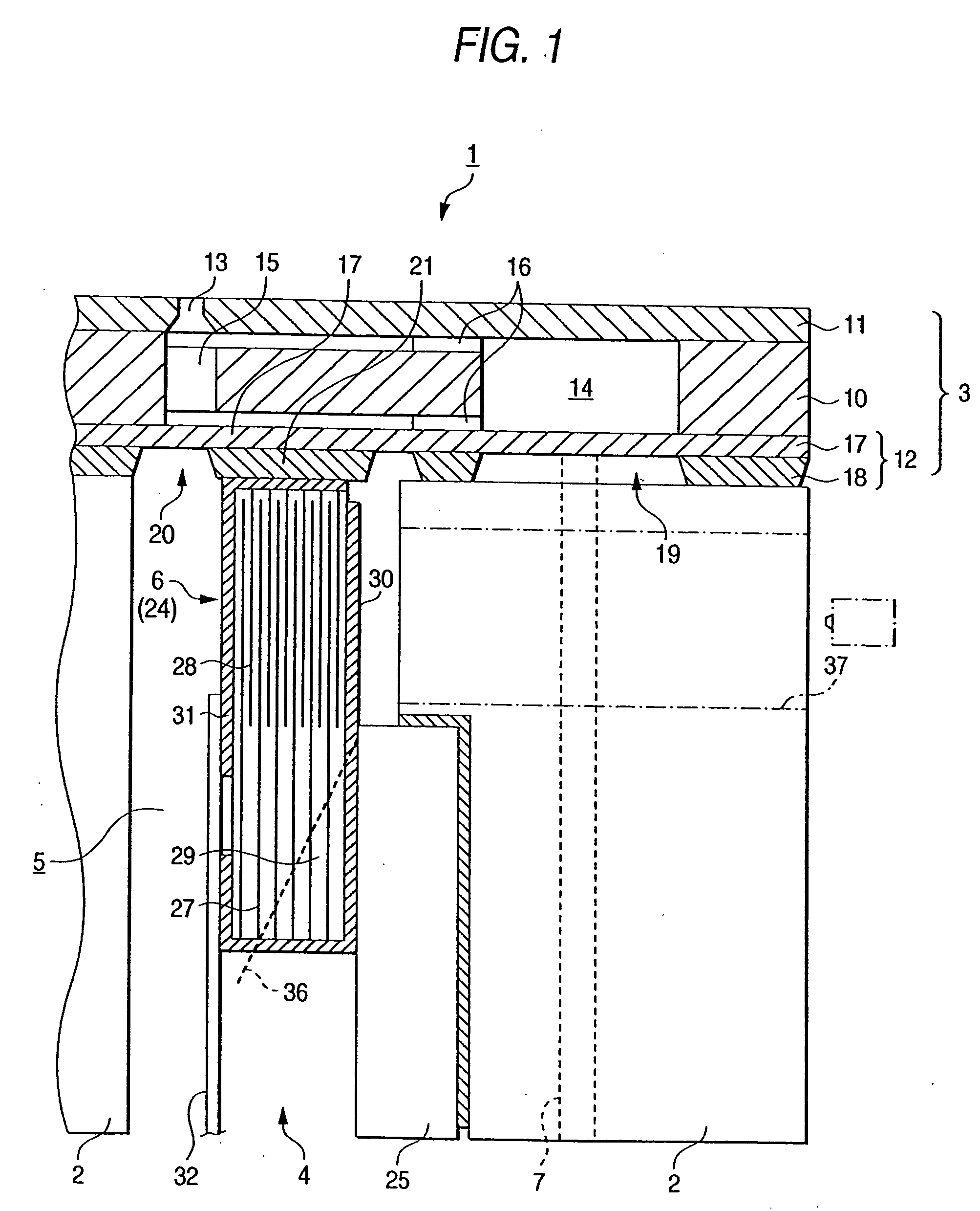
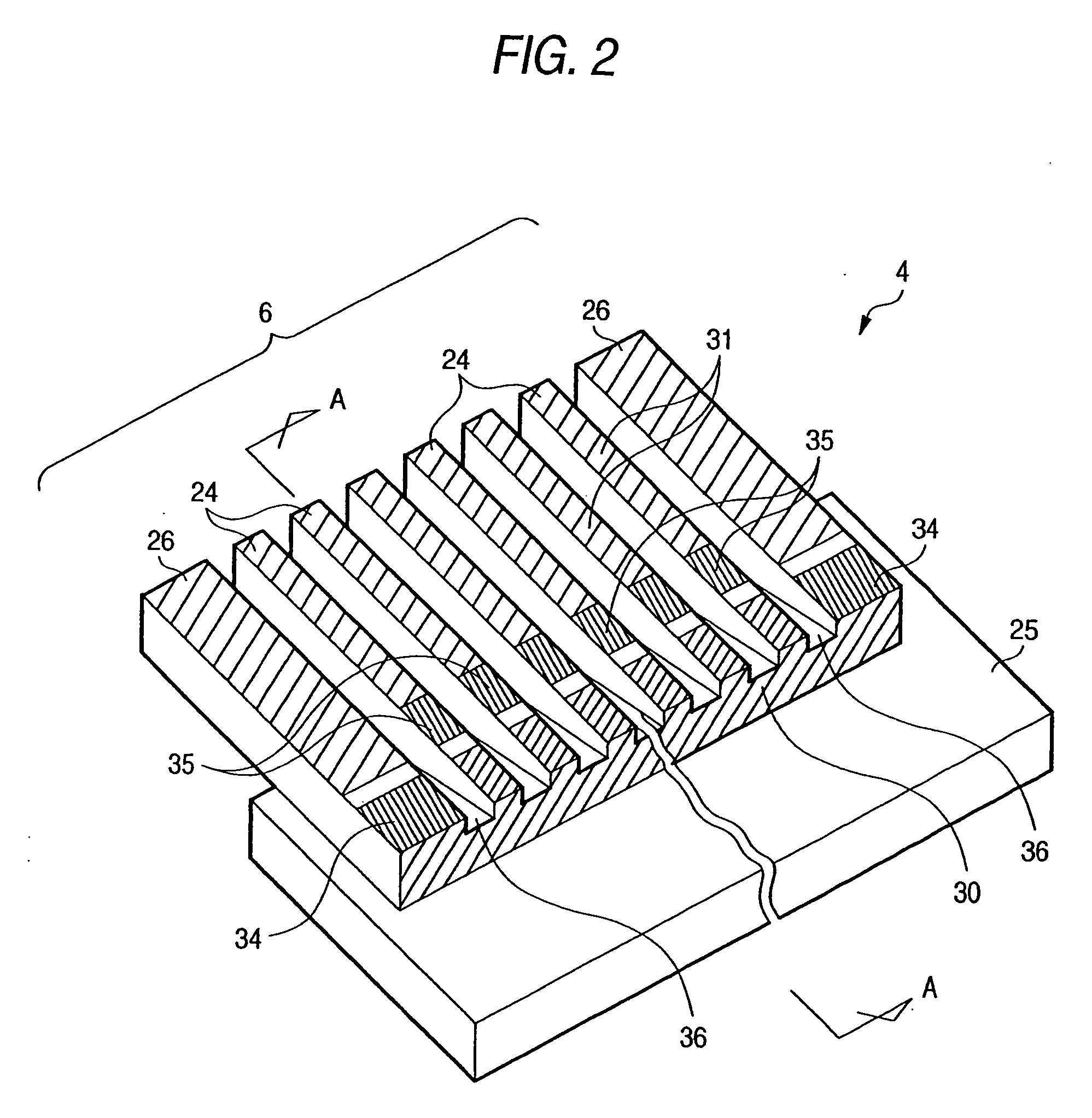
[0171] In the manufacturing method, first a piezoelectric vibrator unit 4 is manufactured. A plate-like laminate member is manufactured as in the That is, the common internal electrodes 27 and the segment internal electrodes 28 are laminated alternately with the piezoelectric material 29 interposed between adjacent internal electrodes so that the active region is formed in the free end part 24a, thereby manufacturing a plate-like laminate substrate. A segment external electrode 31 and a common external electrode 30 are formed on the surface or surfaces of the laminate substrate, thereby manufacturing a laminate member provided with the external electrodes. If the laminate member is manufactured, a fixing plate 25 is joined to the fixing plate attachment surface of the laminate member, and the laminate member is cut to have teeth of comb teeth, i.e. a plurality of the piezoelectric vibrators 24 and 26.

[0172] If the piezoelectric vibrator unit 4 is manufactured, a case 2 and a flow p...

third embodiment

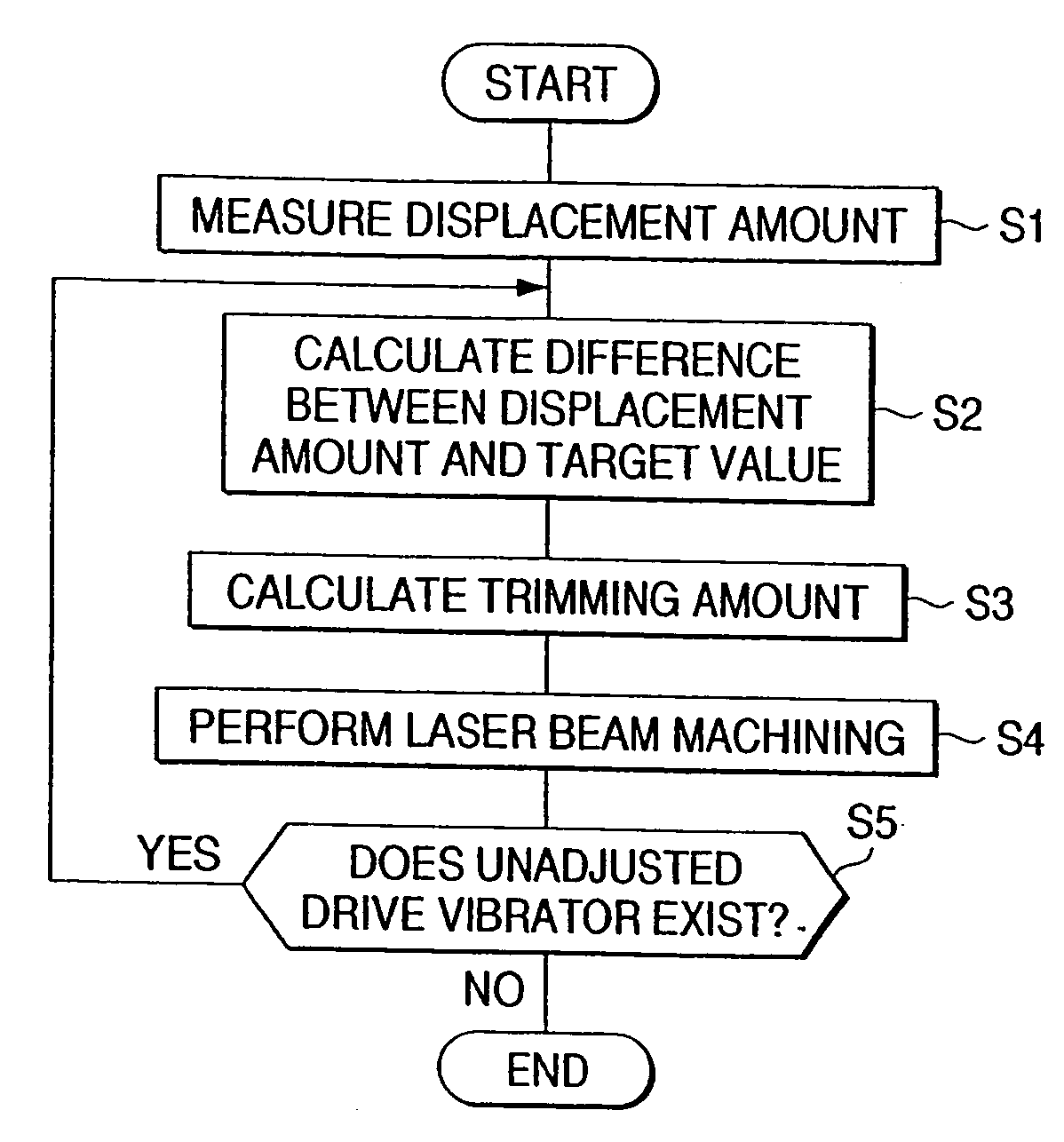
[0178] Although each of the above-described embodiments executes trimming of the trimming portions to adjust the displacement amounts of the drive vibrators 24 (24A), thereby making the ink droplet ejection amounts uniform, the invention is not limited thereto or thereby. For example, the polarization state of piezoelectric material 29 forming a part of the drive vibrator can also be adjusted for adjusting the displacement amount. the invention wherein the polarization state is adjusted will be discussed.

[0179] The third embodiment slightly differs in piezoelectric vibrator configuration from the above-described embodiments. That is, as shown in FIG. 8, a drive vibrator 24B of the third embodiment has no trimming portion, and the surface, corresponding in location to the trimming portion, is covered with the external electrode. Other parts of the third embodiment are similar to those of the first and second embodiments, and therefore identical parts are denoted by the same reference...


PUM

PropertyMeasurementUnit
widthaaaaaaaaaa
displacementaaaaaaaaaa
polarityaaaaaaaaaa

Abstract

Common internal electrodes 27 and segment internal electrodes 28 are laminated alternately with a piezoelectric material 29 between and a common external electrode 30 and a segment external electrode 31 are provided on the surface, forming a drive vibrator 24. A free end part 24a of the drive vibrator 24 is formed with an active region L and can be expanded and contracted in the length direction of the vibrator. A piezoelectric material 29 of the outermost layer in the free end part 24a can be operated based on the potential difference between the external and internal electrodes and a portion of the active region L in the external electrode is used as a trimming portion with an effective length x varied by trimming.

Description

[0001] This is a divisional of application Ser. No. 09 / 748,104 filed December 27, 2000; the disclosure of which is incorporated herein by reference.BACKGROUND OF THE INVENTION [0002] This invention relates to a liquid jet unit used in an industrial machine, such as a manufacturing machine for manufacturing optical filters, and an image recording apparatus such as a plotter and a printer, and a piezoelectric vibrator unit used in the liquid jet unit. This invention also relates to methods of manufacturing the liquid jet unit and the piezoelectric vibrator unit. [0003] Industrial machines such as manufacturing machines and image recording apparatuses such as plotters and printers are available, which employ a liquid jet head for ejecting liquid in the form of liquid droplets. For example, an industrial machine for manufacturing an optical filter is designed to eject color material in the form of liquid droplets onto a filter substrate using an ejection head (a kind of liquid jet head)...

Claims


Application Information

Patent Timeline
Patent Type & Authority Applications(United States)
IPC IPC(8): H04R17/00B41J2/16G01M99/00H01L41/047H01L41/083
CPCB06B1/0607B41J2/14274B41J2/1612B41J2/1623B41J2/1626B41J2/1632Y10T29/49771H01L41/047H01L41/083Y10T29/42Y10T29/49774Y10T29/49004Y10T29/49401B41J2/1634H10N30/872H10N30/045H10N30/063
Inventor KITAHARA, TSUYOSHI
Owner SEIKO EPSON CORP
Why Eureka
Try Eureka