Chiller system with low capacity controller and method of operating same

a controller and low-capacity technology, applied in the field of chilling water systems, can solve the problems of low capacity demand, lower kilowatt-per-ton use, and less efficient operation of chillers, and achieve the effect of low capacity, low capacity, and low cos

Inactive Publication Date: 2006-01-19
AIR MATRIX MANAGEMENT
View PDF7 Cites 76 Cited by
  • Summary
  • Abstract
  • Description
  • Claims
  • Application Information

AI Technical Summary

Benefits of technology

[0011] Accordingly, it is an advantage of the present invention that a method and low capacity controller are provided for operating a chiller system.
[0012] It is another advantage of the present invention that a method and low capacity controller are provided that enable a chiller system to be operated below a minimum allowable capacity for the chiller system.
[0013] Yet another advantage of the present invention is that the low capacity controller can be readily and cost effectively incorporated into a chiller system.
[0014] The above and other advantages of the present invention are carried out in one form by a method of operating a chiller system, the chiller system including a chiller and a fluid loop, and the fluid loop including a supply line for conveying a fluid from the chiller and a return line for returning the fluid to the chiller. The method calls for determining a capacity demand for the chiller. When the capacity demand is less than a minimum allowable capacity of the chiller, the fluid is warmed in the return line to establish a false capacity demand, detectable at the chiller, that is at least the minimum allowable capacity.
[0015] The above and other advantages of the present invention are carried out in another form by a low capacity controller in a chiller system. The chiller system includes a chiller and a first fluid loop, the first fluid loop including a supply line for conveying a chiller fluid from the chiller and a return line for returning the chiller fluid to the chiller, the chiller being operable above a minimum allowable capacity for the chiller. The low capacity controller includes a heater, and a secondary loop interposed between the return line and the heater. The low capacity controller further includes means for enabling a transfer of the chiller fluid through the heater via the secondary loop when a capacity demand is less than the minimum allowable capacity, the chiller fluid being warmed at the heater, and means for returning the chiller fluid from the heater to the return line via the secondary loop.

Problems solved by technology

However, much of the time that a chiller is in use, it is operating at less than full load.
Indeed, a chiller system in a building may operate over a wide range of demand conditions, with significant dominance of low capacity demand.
Low capacity demand can result from seasonal fluctuations, when cooling a small office or zone during “off-hours”, when there is low or no load available for the start up of the chiller system, and so forth.
Low capacity demand typically causes a chiller to operate less efficiently.
That is, lower capacity demand results in a higher kilowatt use per ton.
More critically however, low capacity demand can force a chiller system to operate in unstable conditions.
Left unchecked, the eventual result is coil frosting and compressor flooding.
Accordingly, some chillers are unable to operate when the capacity demand is very low.
This is problematic for an operator who wishes to cool a small office or zone during “off-hours”, who needs to keep one office or room open past normal closing time, who has low or no load available for the start up of the chiller system, and so forth.
Moreover, hot gas bypass can undermine the reliable operation of a chiller by introducing problems stemming from insufficient oil return and refrigerant logging in the hot gas bypass line.
In addition, hot gas bypass requires an additional refrigerant line thus increasing the initial cost of a chiller system, and also increasing the likelihood of refrigerant leaks.
Hot gas bypass further reduces operating efficiency because the bypassed vapor does no useful cooling.

Method used


Image

  • Chiller system with low capacity controller and method of operating same
  • Chiller system with low capacity controller and method of operating same
  • Chiller system with low capacity controller and method of operating same

Examples


Embodiment Construction

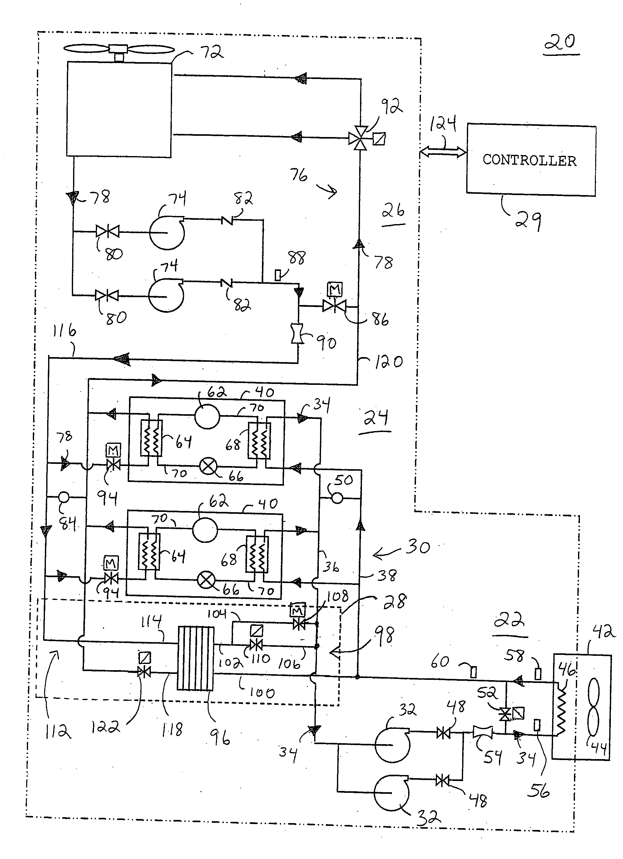
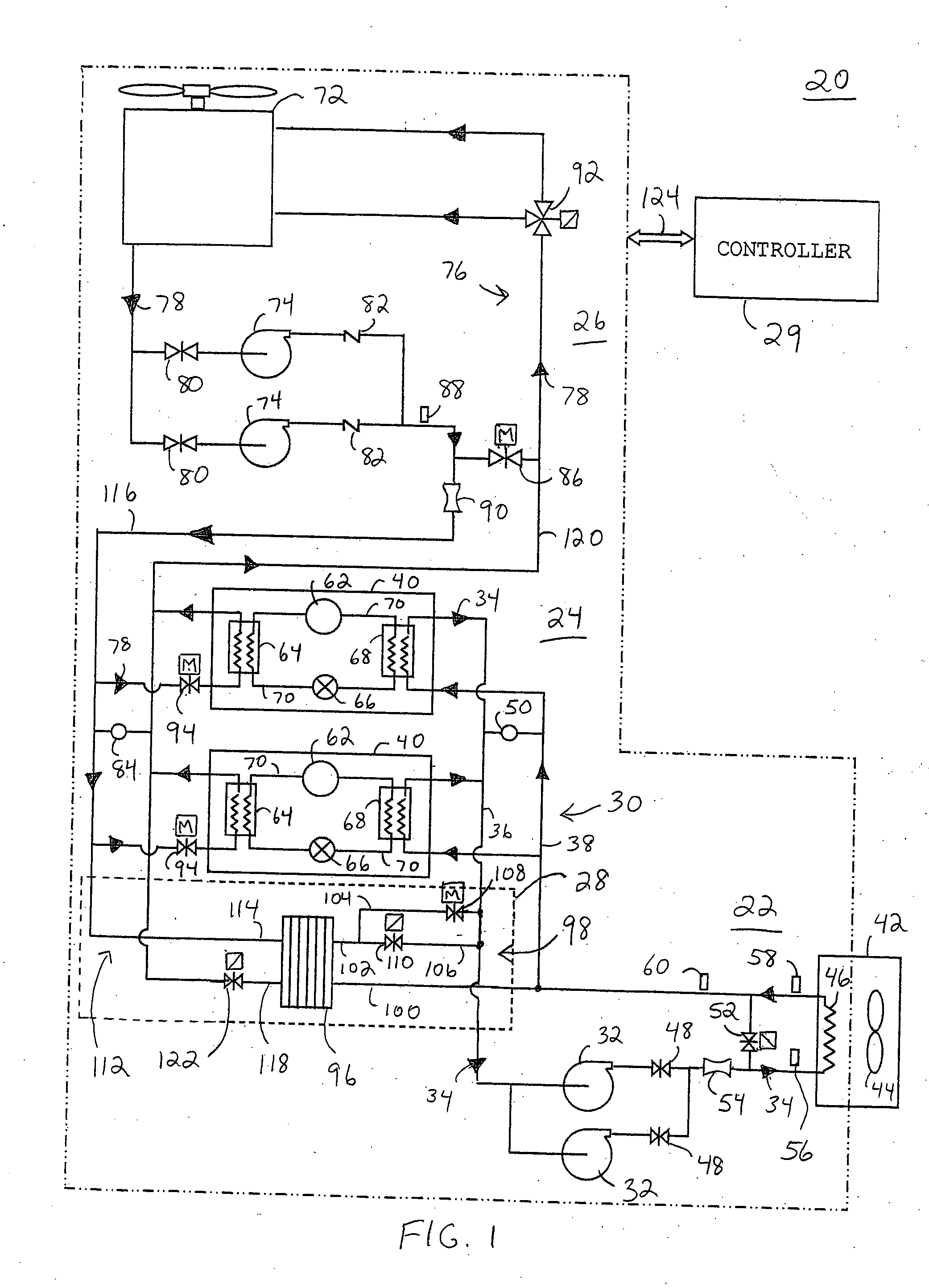
[0023]FIG. 1 shows a block diagram of a chiller system 20 in accordance with a preferred embodiment of the present invention. In general, chiller system 20 includes a chiller fluid section 22, a refrigeration section 24, a condenser fluid section 26, a low capacity controller 28, and a system controller 29.

[0024] Chiller fluid section 22 includes a chiller fluid loop 30 and pumps 32. Pumps 32 are in fluid communication with chiller fluid loop 30 for forcing a chiller fluid, represented by arrow heads 34, to circulate within chiller fluid loop 30. Chiller fluid loop 30 includes a supply line 36 and a return line 38. Supply line 36 conveys chiller fluid 34 from chillers 40 of refrigeration section 24 to an air handler 42 for conditioning the air within a space served by air handler 42. Air handler 42 uses chiller fluid 34 to transfer heat energy from the air being circulated from the space by means of a fan 44 and ductwork (not illustrated) to a heat exchange coil 46 of chiller fluid...


PUM


Abstract

A method (126) and a low capacity controller (28) enable a chiller system (20) to operate below a minimum allowable capacity. The chiller system (20) includes a chiller (40) and a chiller fluid loop (30), having a supply line (36) for conveying a chiller fluid (34) from the chiller (40) and a return line (38) for returning the chiller fluid (34) to the chiller (40). A capacity demand for the chiller (40) is determined. When the capacity demand is less than a minimum allowable capacity of the chiller (40), the chiller fluid (34) is routed from the return line (38) to a heat exchanger (96) of the low capacity controller (28) where the chiller fluid (34) is warmed and returned to the return line (38). The warmed chiller fluid (34) establishes a false capacity demand, detectable at the chiller (40), that is at least the minimum allowable capacity.

Description

TECHNICAL FIELD OF THE INVENTION [0001] The present invention relates to the field of chilled water systems. More specifically, the present invention relates to a method of operating a chilled water system. BACKGROUND OF THE INVENTION [0002] Chiller systems provide a temperature conditioned fluid, for use in conditioning the air within large buildings and other facilities. The chilled fluid is typically pumped to a number of remote heat-exchangers or system coils for cooling various rooms or areas within a building. A chiller system enables the centralization of the air conditioning requirements for a large building or complex of buildings by using water or a similar fluid as a safe and inexpensive temperature transport medium. [0003] In general, a chiller of the chiller system provides chilled water of a particular temperature, via a first fluid loop, for cooling air in a building. Heat is extracted from the building air, transferred to the fluid in the first fluid loop, and is ret...

Claims


Application Information

Patent Timeline
Patent Type & Authority Applications(United States)
IPC IPC(8): F25D17/02
CPCF24F3/06F25D17/02F24F2221/54F24F11/006F24F11/30F24F11/62F24F11/74
Inventor DOMINGUEZ, DANIEL
Owner AIR MATRIX MANAGEMENT
Why Eureka
Try Eureka