Method and apparatus for cooling engines in buildings at oil well sites and the like

a technology for cooling engines and oil wells, applied in the direction of liquid cooling, engine components, cooling system control, etc., can solve the problems of large loss of energy, overheating problems, and relatively inefficient internal combustion engines, and achieve economical and convenient connection, reduce problems, and convenient to use

Inactive Publication Date: 2006-01-19
HAYES GERALD
View PDF22 Cites 44 Cited by
  • Summary
  • Abstract
  • Description
  • Claims
  • Application Information

AI Technical Summary

Benefits of technology

[0013] The present invention provides an auxiliary cooling system that allows the stationary internal combustion engine to maintain all of the benefits of being housed within a building while at the same time reducing the problems that occur when an engine is operated in a warm confined space. A portion of the engine's coolant is routed to an auxiliary heat exchanger or radiator located outside the building. The coolant that is routed through the auxiliary heat exchanger passes through the auxiliary heat exchanger and is routed back into and through the internal combustion engine. Because these stationary internal combustion engines are typically slightly modified vehicle engines and the plumbing for a heater core is in place, it is economical and convenient to connect the auxiliary cooling system to the stationary internal combustion engine using the heater hose connections.
[0014] The auxiliary heat exchanger can be readily provided by an economically available conventional engine radiator of approximately the desired size, since precision in sizing is not contemplated to be critical. Further, many vehicle engines operate their conventional cooling fans with electric motors, and such electric powered fans are also readily available at an economical cost. The auxiliary cooling system of the invention can thus be readily provided at an economical cost, and provide added cooling that reduces the risk of over-heating and engine shut down or damage.

Problems solved by technology

The engines, being stationary in a closed-in space and operating for extended periods of time, suffer from overheating problems during warm weather when the ambient temperature of the air surrounding the engine is high and the cooling system of the engine is insufficient to cool the engines.
Internal combustions engines are relatively inefficient and tend to lose a lot of energy in the form of heat.
This loss of energy in the form of heat necessitates the use of a cooling system for the internal combustion engine.
Stationary engines in enclosed spaces suffer from disadvantages usually not present in engines mounted in moving vehicles.
On warm days the temperature inside these buildings can get quite high, reducing the effectiveness of the engine's cooling system and increasing the risk of overheating.
Often these well sites are only visited once a day and so considerable production can be lost.
Where the production fluid pumped from the well comprises a considerable amount of sand, as is common in some areas, the sand can settle and make the pump difficult to restart, and possibly require that the well be flushed before the pump can be restarted.
Such removal is not typically very effective since the thermostats are generally running wide open in any event.
Removing the roof or building exposes the equipment inside to the elements, and is time consuming and involves considerable labor.

Method used


Image

  • Method and apparatus for cooling engines in buildings at oil well sites and the like
  • Method and apparatus for cooling engines in buildings at oil well sites and the like

Examples


Embodiment Construction

:

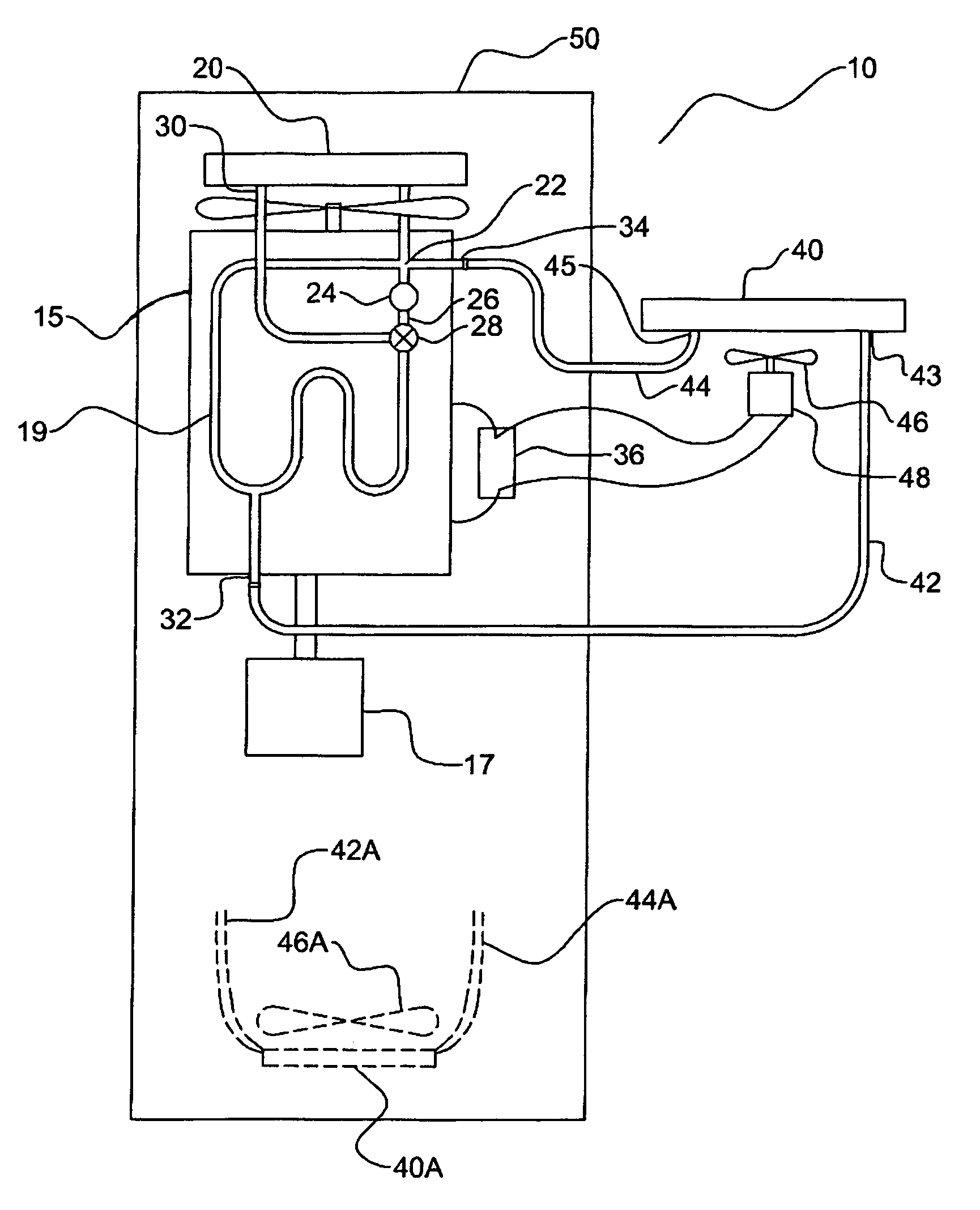
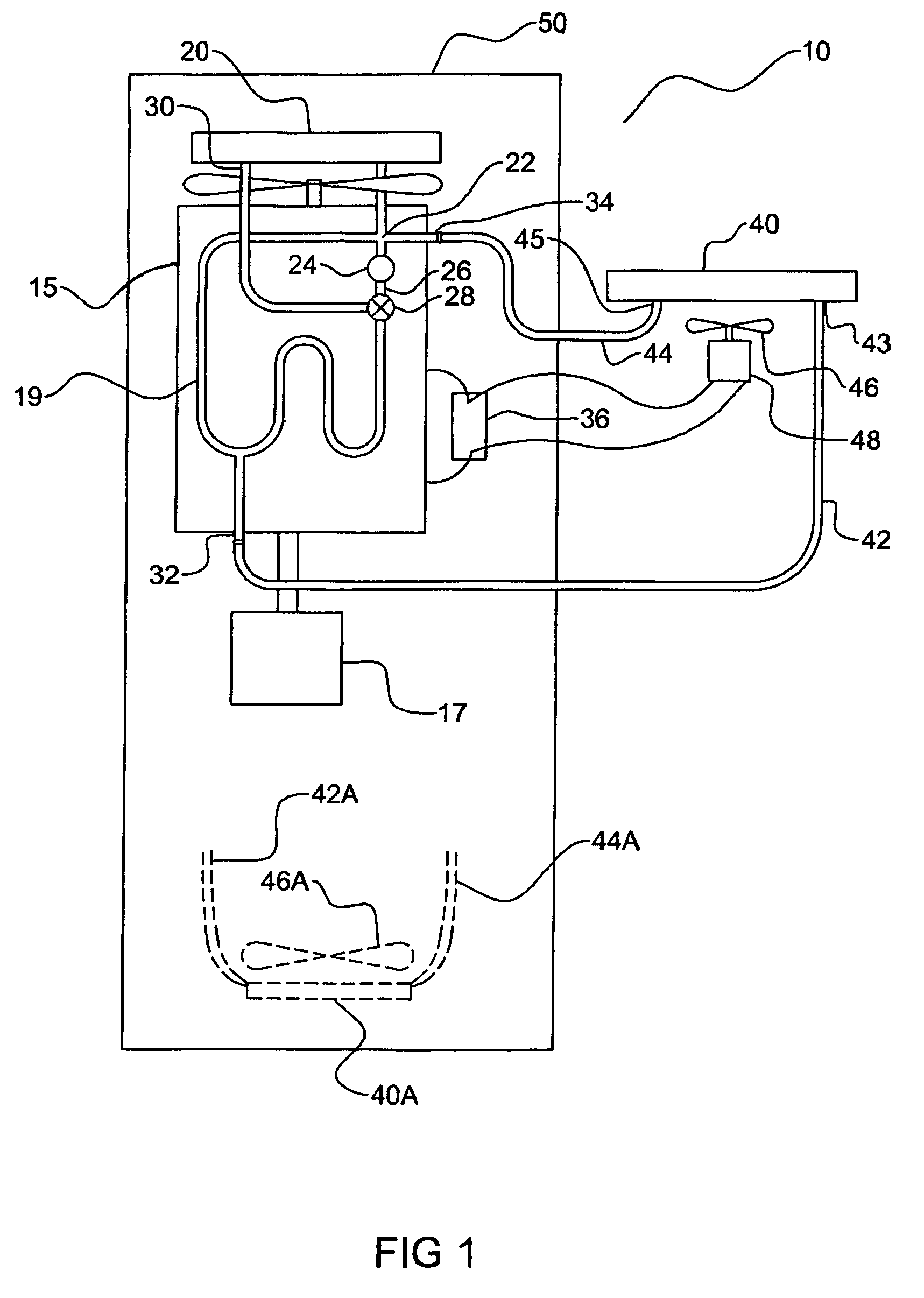
[0019]FIG. 1 schematically illustrates a stationary internal combustion engine system, incorporating an auxiliary cooling system 10 of the present invention. The stationary internal combustion engine system comprises a stationary internal combustion engine 15 located within a protective building 50 which serves to protect equipment including the engine 15 and typically other equipment. The illustrated engine 15 is connected to an auxiliary cooling system 10 to provide added cooling of the engine and reduce over-heating.

[0020] The engine 15 is a stationary internal combustion engine and is used to power a device, for example a hydraulic pump 17 that drives a rotary pump in an oil well, that is connected to the drive shaft of the engine 15. The engine 15 has a cooling system comprising a heat exchanger in the form of a main radiator 20 connected to the intake 22 of a pump 24. The pump output 26 is connected to a thermostat valve 28 which initially at start up is closed and directs a...


PUM


Abstract

An enclosed engine apparatus with auxiliary cooling includes a liquid cooled internal combustion engine located in a building. An auxiliary heat exchanger is operative to transfer heat from a liquid coolant flowing through the auxiliary heat exchanger to an air stream passing through the auxiliary heat exchanger, and the auxiliary heat exchanger is located outside the building. A supply conduit connects to the engine cooling system at a heater supply fitting on the engine and to a supply port of the auxiliary heat exchanger, and a return conduit connects to the cooling system at a heater return fitting on the engine and to a return port of the auxiliary heat exchanger. An electric fan is powered draws air through the auxiliary heat exchanger.

Description

[0001] This application claims priority of Canadian Application No. 2,474,415, filed Jul. 15, 2004. The contents of which are hereby incorporated in their entireties by reference into this application. [0002] This invention is in the field of cooling engines, and in particular for cooling stationary engines located inside a building at an oil well side or the like. BACKGROUND [0003] A typical oil and gas well site will often include an internal combustion engine to provide power for certain apparatuses present at the site such as a hydraulic pump which in turn powers a hydraulic motor, which will rotate a pump in the well. These internal combustion engines are typically multi-cylinder engines such as inline 6s, V-6s and V-8s and commonly automobile engines that have been modified for stationary use. These engines are typically housed within a protective building at the well site location, where the engines typically run at a relatively low, steady RPM for extended periods of time. T...

Claims


Application Information

Patent Timeline
Patent Type & Authority Applications(United States)
IPC IPC(8): F01P7/10
CPCF01P5/04F01P3/18
Inventor HAYES, GERALD
Owner HAYES GERALD
Why Eureka
Try Eureka