Eureka AIR delivers breakthrough ideas for toughest innovation challenges, trusted by R&D personnel around the world.

Micro-channel heat sink

Inactive Publication Date: 2006-01-19
THORRN MICRO TECH
View PDF21 Cites 21 Cited by
  • Summary
  • Abstract
  • Description
  • Claims
  • Application Information

AI Technical Summary

Problems solved by technology

It is well known that heat can be a problem in many environments, and that overheating can lead to failures of components such as integrated circuits (e.g. a central processing unit (CPU) of a computer) and other electronic components.
However, dissipating heat using a gas, such as air, is difficult because of the poor thermal conductivity of gases.
Gases also have a low heat capacity, which causes them to heat up quickly, which retards the rate of heat absorption by decreasing the temperature difference between the gas and the heat sink.
Conventional heat sinks have a limited amount of surface area that can be put into a given volume, and as a result, an adequate conventional heat sink must be large in order to provide the necessary convection surface area.
Additionally, these heat sink designs do not integrate well with certain types of fluid pump designs.
However, these references do not fully solve the problems associated with effective cooling of electronic components as described above.
However, there are two major obstacles to the practical implementation of a micro-channel concept in a heat sink application.
Second, the low heat capacity of gases means that they heat up quickly and become ineffective at dissipating heat.

Method used


Image

  • Micro-channel heat sink
  • Micro-channel heat sink
  • Micro-channel heat sink

Examples


Embodiment Construction

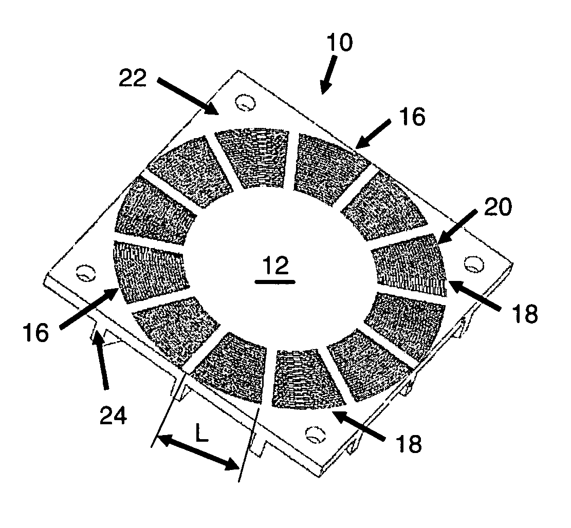
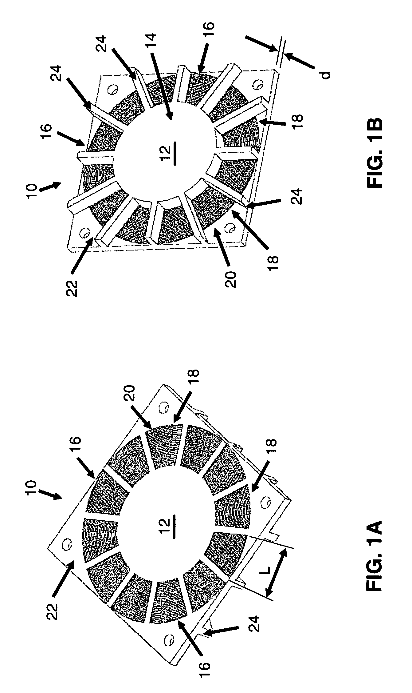
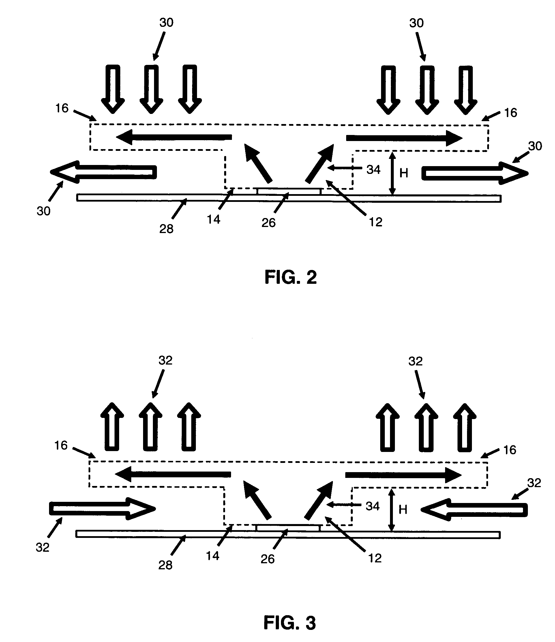
[0023] The present invention will now be described in detail with reference to the figures of the drawing, which are provided as illustrative examples of the invention so as to enable those skilled in the art to practice the invention. Notably, the figures and examples below are not meant to limit the scope of the present invention to a single embodiment, but other embodiments are possible by way of interchange of some or all of the described or illustrated elements. Moreover, where certain elements of the present invention can be partially or fully implemented using known components, only those portions of such known components that are necessary for an understanding of the present invention will be described, and detailed descriptions of other portions of such known components will be omitted so as not to obscure the invention. In the present specification, the present invention is to include multiple components as well as a single component when only one is shown, and vice versa,...


PUM


Abstract

A heat sink with an arrangement of a plurality of micro-fins, spaced apart to form microchannels through which a gas can flow. The heat sink includes a conductive apparatus for conducting heat from a heat source to the arrangement of micro-fins. The conductive apparatus includes a post, with a bottom surface at a proximal end for contact with a heat source. The arrangement extends radially outward from the post at a more distal end spaced apart from the bottom surface of the post. In one embodiment, the conductive apparatus includes a plurality of ribs extending radially outward from the post. Each micro-fin has a length that bridges the space between two ribs. The micro-fins are spaced substantially parallel to each other to form micro-channels for passage of cooling gas. Another embodiment includes a plurality of micro-fins extending substantially perpendicularly outward from the post, and separated to form micro-channels. Another embodiment includes a plurality of micro-fins extending substantially perpendicular to a rectangular post. In operation, heat is conducted from the heat source, through the post to the micro-fins, and into gas around each micro-fin. A fan or other gas pump can be used to force a flow of the gas through the micro-channels and thereby through the arrangement.

Description

CROSS-REFERENCE TO RELATED APPLICATIONS [0001] The present application is based on, and claims priority from, U.S. Provisional Patent Appln. No. 60 / 588,001 filed Jul. 13, 2004, the contents of which are incorporated herein by reference in their entirety.FIELD OF THE INVENTION [0002] The present invention relates generally to cooling of electronic components, and more particularly to heat sinks with air cooled fins for cooling electronic components such as integrated circuits. BACKGROUND OF THE INVENTION [0003] It is well known that heat can be a problem in many environments, and that overheating can lead to failures of components such as integrated circuits (e.g. a central processing unit (CPU) of a computer) and other electronic components. [0004] Heat sinks are a common device used to prevent overheating, and mainly rely on the dissipation of heat from the device using air. However, dissipating heat using a gas, such as air, is difficult because of the poor thermal conductivity of...

Claims


Application Information

Patent Timeline
IPC IPC(8): H05K7/20
CPCH01L23/367H01L23/427H01L23/467H01L2924/0002H01L2924/00
Inventor SCHLITZ, DANIEL JON
Owner THORRN MICRO TECH
Why Eureka
Eureka Blog
Learn More