Minimizing effects of tolerance stack-up in damper valve assemblies

a technology of damper valve and tolerance stack, which is applied in the direction of spring/damper, shock absorber, vibration damper, etc., can solve the problems of increasing scrap, adversely affecting the damper's damping characteristics, and undesirable variability within manufactured lots, so as to reduce variations

Inactive Publication Date: 2006-01-19
ARVINMERITOR TECH
View PDF15 Cites 6 Cited by
  • Summary
  • Abstract
  • Description
  • Claims
  • Application Information

AI Technical Summary

Benefits of technology

[0006] Accordingly, the above mentioned provides a damper design that provides consistent loading of the damper valve bodies by reducing variations due to tolerance stack-ups.

Problems solved by technology

The damping characteristics of the damper are adversely affected if the deflection discs are not properly loaded against the piston.
Tolerance stack-ups in the valve assembly components can cause variability in the performance characteristics of the valves within a manufactured lot of valve assemblies, which can increase scrap.
Variability within manufactured lots is also undesirable because customers are increasingly requiring valve assemblies to be manufactured to tight performance tolerances.

Method used


Image

  • Minimizing effects of tolerance stack-up in damper valve assemblies
  • Minimizing effects of tolerance stack-up in damper valve assemblies
  • Minimizing effects of tolerance stack-up in damper valve assemblies

Examples


Embodiment Construction

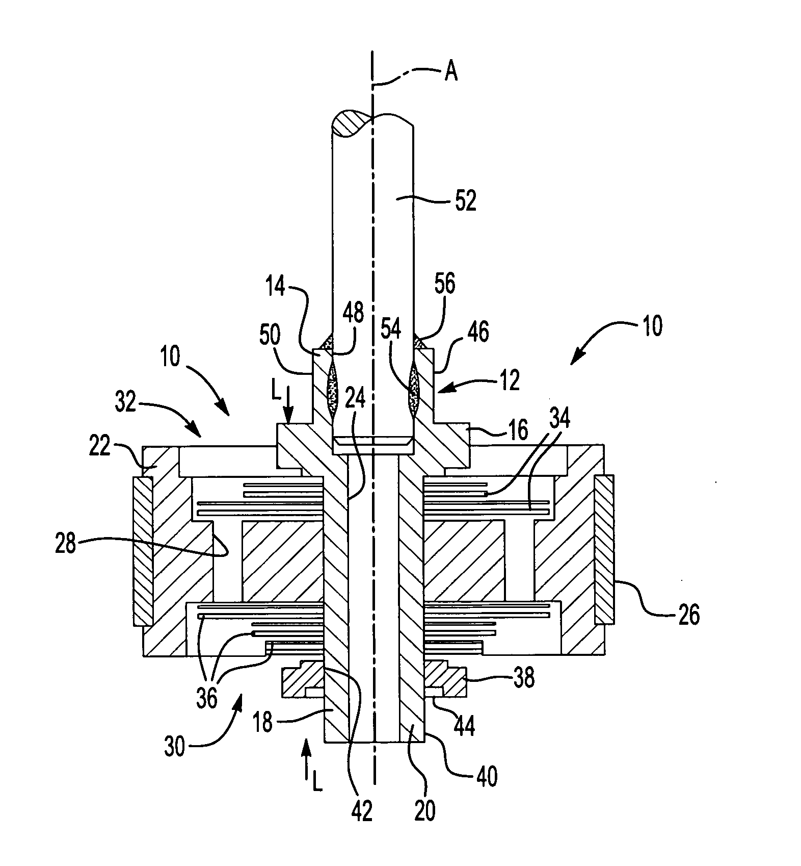
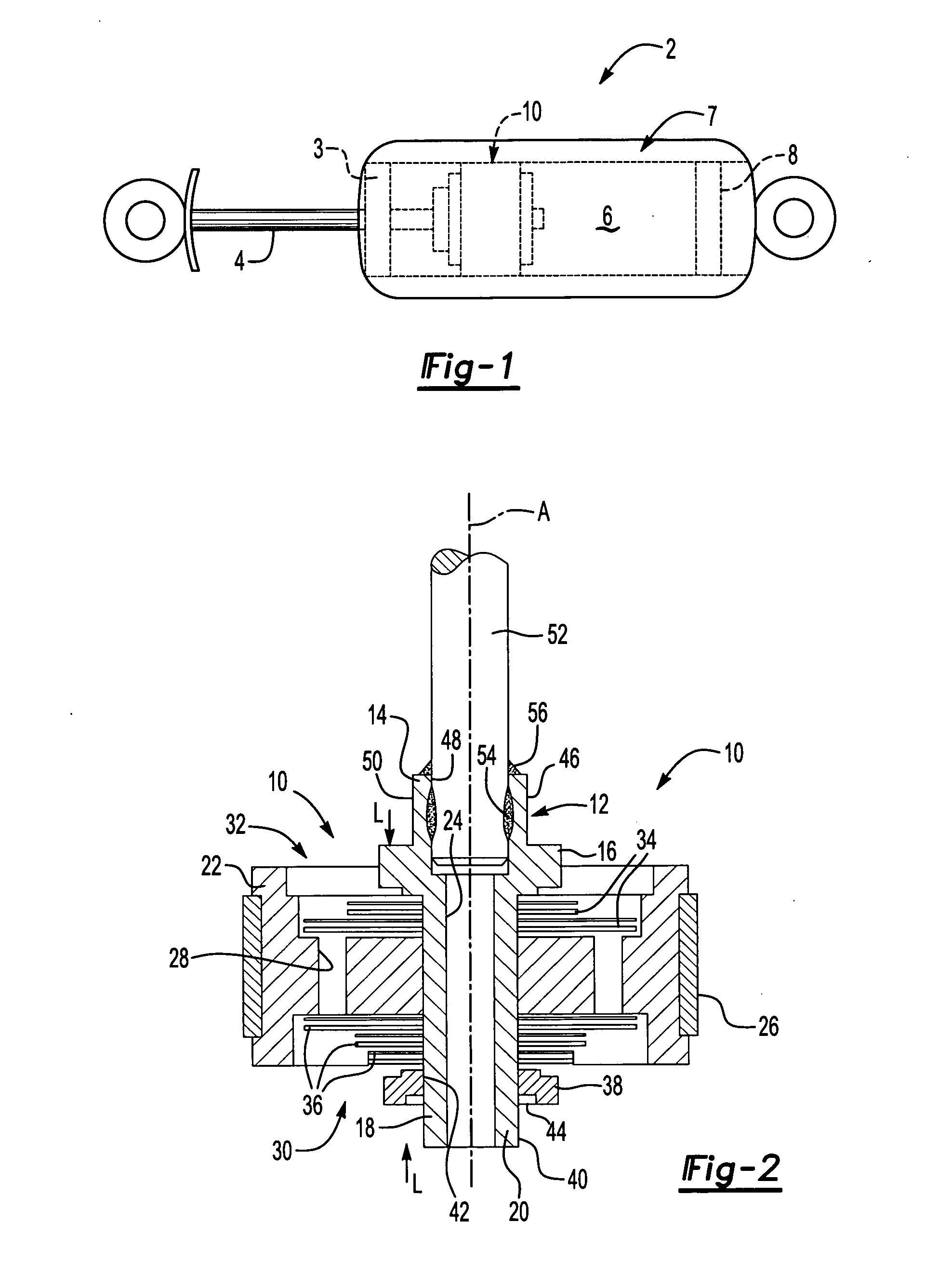
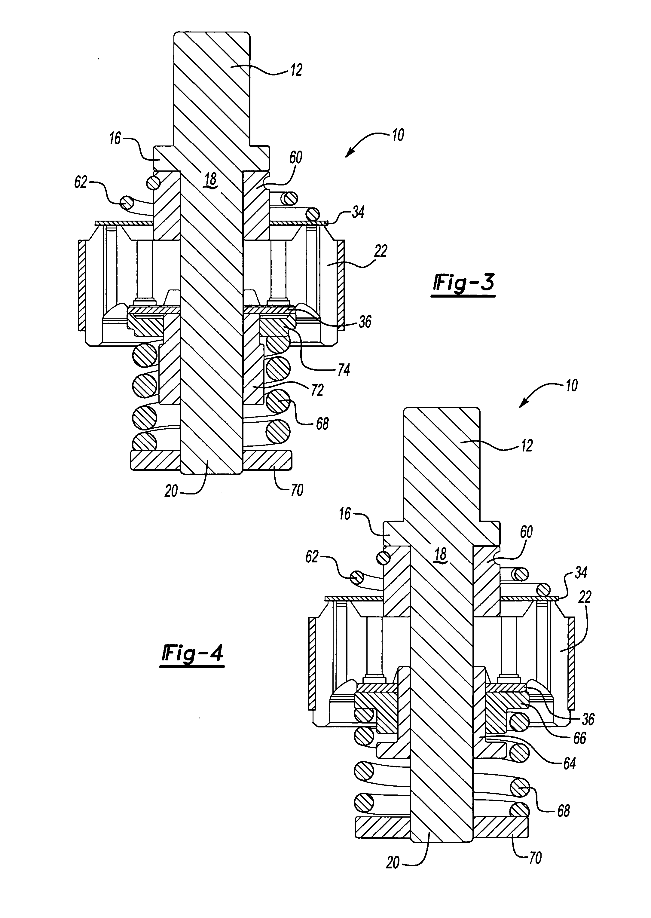
[0012] A twin tube shock absorber 2 is shown in FIG. 1. The shock absorber 2 schematically depicts a cylinder head 3 at one end slidingly receiving a rod 4, as is well known in the art. An end of the rod 4 is secured to the inventive piston valve assembly 10, which is arranged in a fluid chamber 6. During a compression stroke, the piston valve assembly 10 moves towards a base valve 8, which regulates the flow of fluid from the fluid chamber 6 to an outer chamber 7. As will be appreciated from the description below, the piston assembly 10 incorporates an inventive hub 12, which is shown in FIGS. 2-4.

[0013] A piston valve assembly 10 of the present invention is shown in FIG. 2. The assembly 10 may be used in a monotube or a twin tube shock absorber. The assembly 10 includes a hub 12 that is designed to be used with different sized pistons and deflection discs to facilitate a more modular damper assembly. However, it should be understood that the inventive clamping arrangement may als...


PUM


Abstract

A piston valve assembly for a damper comprises a piston having a central hole and a fluid passageway spaced from the hole. A deflection disc having a central aperture is aligned with the hole. The deflection disc is arranged adjacent to the piston and at least partially blocks the fluid passageway for regulating the flow of hydraulic fluid between the fluid chambers when installed in the damper. A hub, common across different dampers, includes a neck that is arranged in the hole and the aperture of the deflection disc. A retainer abuts an unthreaded outer surface of the hub. During assembly, the retainer is received on the cylindrical outer surface in a slip fit relation. The deflection disc and pistons are loaded to a predetermined clamp load. The retainer can be positioned axially to account for variability due to tolerance stack-ups. The retainer is secured to the outer surface by a securing material such as a weld bead.

Description

BACKGROUND OF THE INVENTION [0001] This invention relates to dampers such as vehicle suspension shock absorbers, struts and the like. More particularly, the invention relates to a common hub design for piston and base valve arrangements enabling a more modular damper. [0002] Dampers such as shock absorbers and struts are used in vehicles to absorb inputs from the roadway to provide a desirable vehicle ride. Typically, vehicle dampers employ a piston that moves through a cylinder having hydraulic fluid. The fluid flows through fluid passageways and valves in the piston, which absorbs the roadway inputs in the form of heat. One common type of piston valve assembly uses deflection discs on either side of the piston. The deflection discs at least partially block the fluid passages in the piston to regulate the fluid flow rate through the passages during the compression and rebound strokes of the damper. [0003] The piston and deflection discs are secured in abutment with one another by t...

Claims


Application Information

Patent Timeline
Patent Type & Authority Applications(United States)
IPC IPC(8): F16F15/03F16F9/32F16F9/348
CPCF16F9/348F16F9/3228
Inventor CARLSTEDT, ROBERT P.SIESEL, JAMES J.SLEDZ, CHRISTOPHER T.
Owner ARVINMERITOR TECH
Why Eureka
Try Eureka