High-energy ion implanter and method of operation thereof

a high-energy ion and implanter technology, applied in nuclear engineering, separation of dispersed particles, separation processes, etc., can solve the problems of affecting the focusing of the ion beam, unfavorable rise in pressure, and adversely affecting the reliability of the ion implantation process

Inactive Publication Date: 2006-01-19
SAMSUNG ELECTRONICS CO LTD
View PDF3 Cites 12 Cited by
  • Summary
  • Abstract
  • Description
  • Claims
  • Application Information

AI Technical Summary

Benefits of technology

[0017] An object of the present invention is to provide a high-energy ion implanter, and method of operation thereof, in which even slight malfunctions in a tandem accelerator thereof can be sensed.

Problems solved by technology

Such charge exchanging gas may cause an unfavorable rise in the pressure in the low-energy box 361 and / or the high-energy box 371, and may affect the focusing of the ion beam.
This, in turn, may create contamination, cause accidents and may otherwise adversely impact the reliability of the ion implantation process.
However, the vacuum gauges 381 are only capable of revealing remarkable changes in vacuum pressure.
Additionally, monitoring only the turbo pump 337 and associated hardware operation makes it nearly impossible to ascertain whether the charge exchanging gas is flowing into the low-energy box 361 and / or the high-energy box 371 and hence, does not allow for a determination to be made as to whether such an inflow of the charge exchanging gas is affecting the focusing of the ion beam.

Method used


Image

  • High-energy ion implanter and method of operation thereof
  • High-energy ion implanter and method of operation thereof
  • High-energy ion implanter and method of operation thereof

Examples


Embodiment Construction

[0028] The present invention will now be described more fully hereinafter with reference to the accompanying drawings. However, for the sake of clarity, well-known structures and processes will be not described or illustrated in detail. Furthermore, some elements described in detail in the background section will not be described again.

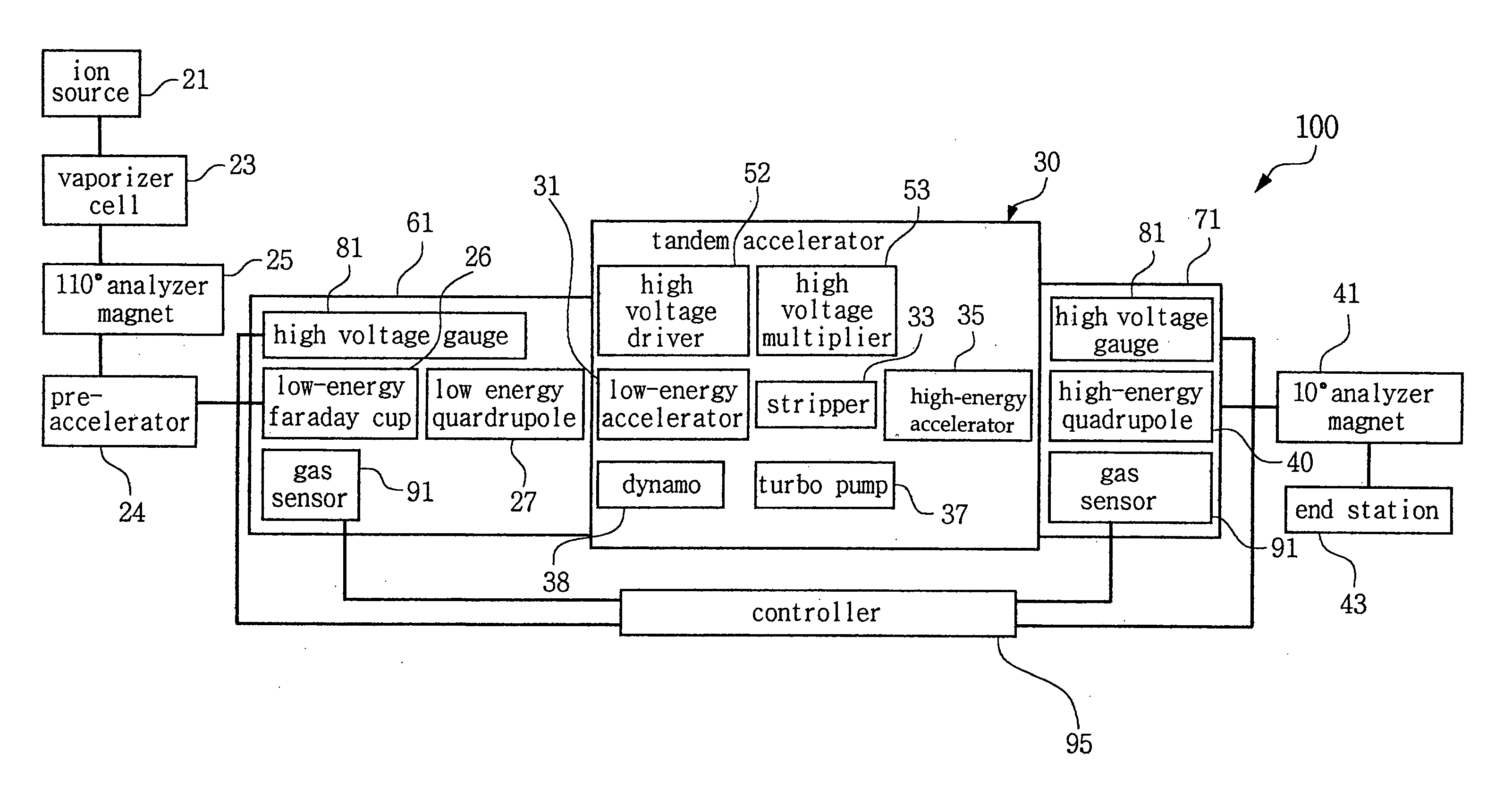
[0029] Referring to FIGS. 4 and 5, the high-energy ion implanter 100 includes a tandem accelerator 30 in which gas sensors 91 are provided. An ion source 21, a vaporizer cell 23, a 110° analyzer magnet 25, and a pre-accelerator 24 are provided at the front end of the tandem accelerator 30. A 10° analyzer magnet 41 and an end station 43 are provided at the rear (downstream) end of the tandem accelerator 30. A controller 95 regulates the above-mentioned respective elements.

[0030] The tandem accelerator 30 has a low-energy accelerator 31, a stripper 33, and a high-energy accelerator 35 that are arranged in series within an accelerating tank 51. A high ...


PUM


Abstract

A high-energy ion implanter monitors the recycling of a charge exchanging gas that is supplied to a stripper of a tandem accelerator. When the charge exchanging gas leaks out from the stripper and then flows into both energy boxes adjacent the tandem accelerator, gas sensors in the energy boxes measure the amount of the charge exchanging gas and send corresponding data to a controller. The controller compares the measured data with a standard data on the charge exchanging gas. When the measured data is different from the standard data, a pre-established interlocking system breaks off the operation of the implanter.

Description

BACKGROUND OF THE INVENTION [0001] 1. Field of the Invention [0002] The present invention generally relates to the fabrication of semiconductor devices. More particularly, the present invention relates to a high-energy ion implanter. [0003] 2. Description of the Related Art [0004] In the fabrication of semiconductor devices, an ion implanter is used to modify surface properties of, for example, a semiconductor wafer. More specifically, the ion implanter ionizes dopant atoms and accelerates them to a high speed. Then, a beam of the ions is swept across the wafer surface. The ions penetrate portions of the wafer that are left exposed by a mask. The amount of dopant and the depth of penetration are governed by the size of the dopant atoms, the velocity of the ions, and the amount of time the wafer is exposed to the beam. [0005] An ion implanter may be classified as a medium-current ion implanter, a high-current ion implanter, or a high-energy ion implanter. The medium-current ion impla...

Claims


Application Information

Patent Timeline
Patent Type & Authority Applications(United States)
IPC IPC(8): H01J37/317H01L21/265
CPCH01J37/3171H01J2237/30405H01J2237/18H01L21/265
Inventor CHO, YEON-HA
Owner SAMSUNG ELECTRONICS CO LTD
Why Eureka
Try Eureka