
Turbo engine

a technology of engine and engine body, applied in the direction of machines/engines, mechanical equipment, instruments, etc., to achieve the effect of reducing downtime, repair cost and repair time, and high stress, reducing downtime and cost of premature maintenan

Inactive Publication Date: 2006-01-19
SIEMENS AG
View PDF16 Cites 3 Cited by
  • Summary
  • Abstract
  • Description
  • Claims
  • Application Information

AI Technical Summary

Benefits of technology

[0010] By means of the invention it is possible for the first time to monitor the state of the blades, in particular continuously even during operation of the turbo engine, and to carry out a timely maintenance and / or overhaul of the turbine, in particular the blades, when a definable wear threshold is reached. As described above, the invention makes use of the effect that charges tend to collect on insulators, whereas on conducting materials they are conducted away by these materials. Charges occur in the flow of fluid materials either when the fluid itself is disassociated into relevant charge carriers, or when relevant charge carriers have been supplied to the fluid. The charge accumulated on an insulating layer may be proportional to its surface area, but is substantially dependent on the surface area. The charge carriers accumulated on the rotating rotor blades generate an electric field whose field strength can be detected by the measuring element. An indication of the field strength can thus be obtained by an analysis of the signals from the measuring element. An intact blade generates in the measuring element a corresponding characteristic amplitude of the measurement signal (e.g. electrical voltage). A worn coating on a rotor blade or a defective coating results in the charge being conducted away via the electrically conducting rotor blade to a reference potential that is electrically connected to the rotor blade. Such a blade can therefore generate a low-amplitude measurement signal in the measuring element. With rotation of the rotor shaft, all the blades of a blade wheel can be directed sequentially past the measuring element, so that it is possible to determine completely the state of the rotor blades of this rotor-blade wheel.
[0027] In order to generate a signal or to generate a criterion for the operation of the turbo engine, for example, it is proposed that the result of the transformation is compared with a definable threshold value. Particularly sensitive and accurate detection of the wear state of a blade can advantageously be achieved in this way. Even a slight reduction, which can be considered as a wear indicator, can be detected, so that appropriate measures can be taken in good time, such as replacing the blade or repairing the coating.

Problems solved by technology

A worn coating on a rotor blade or a defective coating results in the charge being conducted away via the electrically conducting rotor blade to a reference potential that is electrically connected to the rotor blade.

Method used


Image

  • Turbo engine
  • Turbo engine
  • Turbo engine

Examples


Embodiment Construction

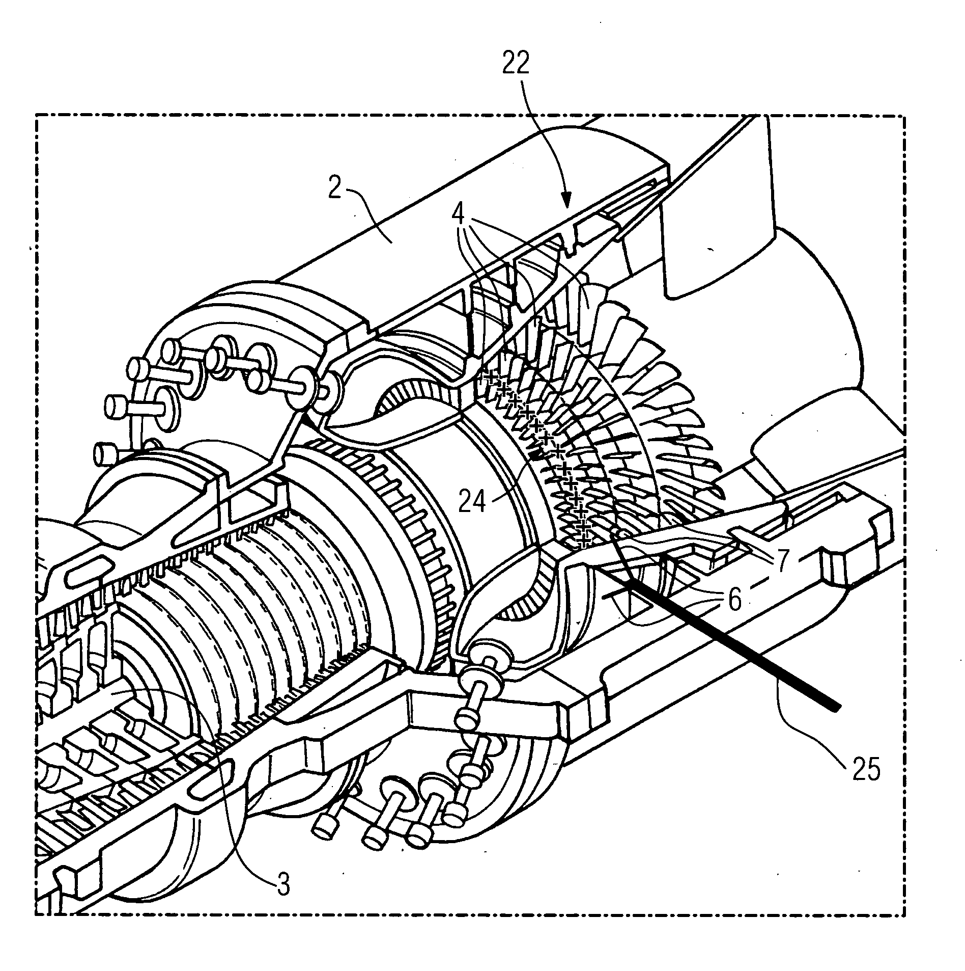
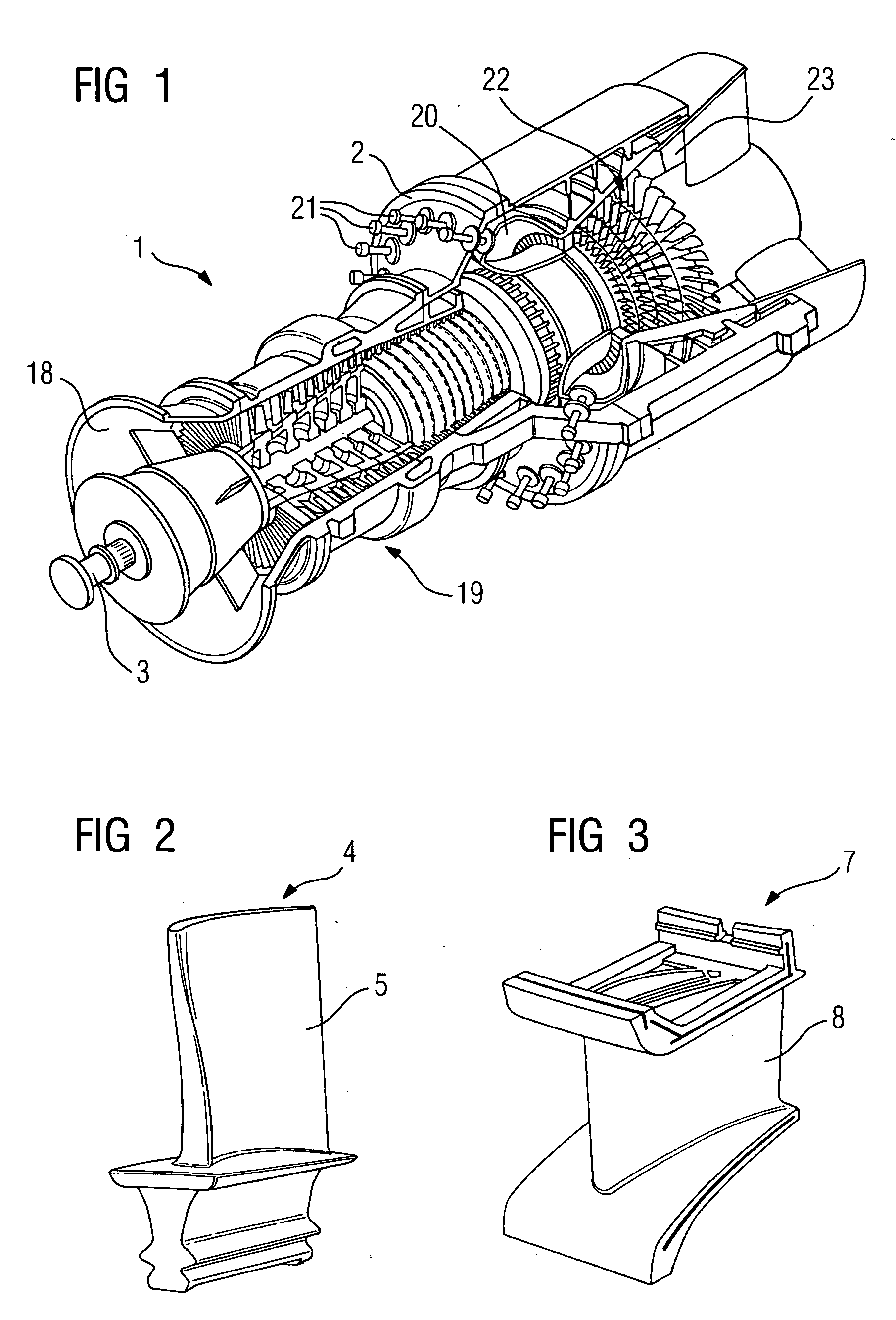
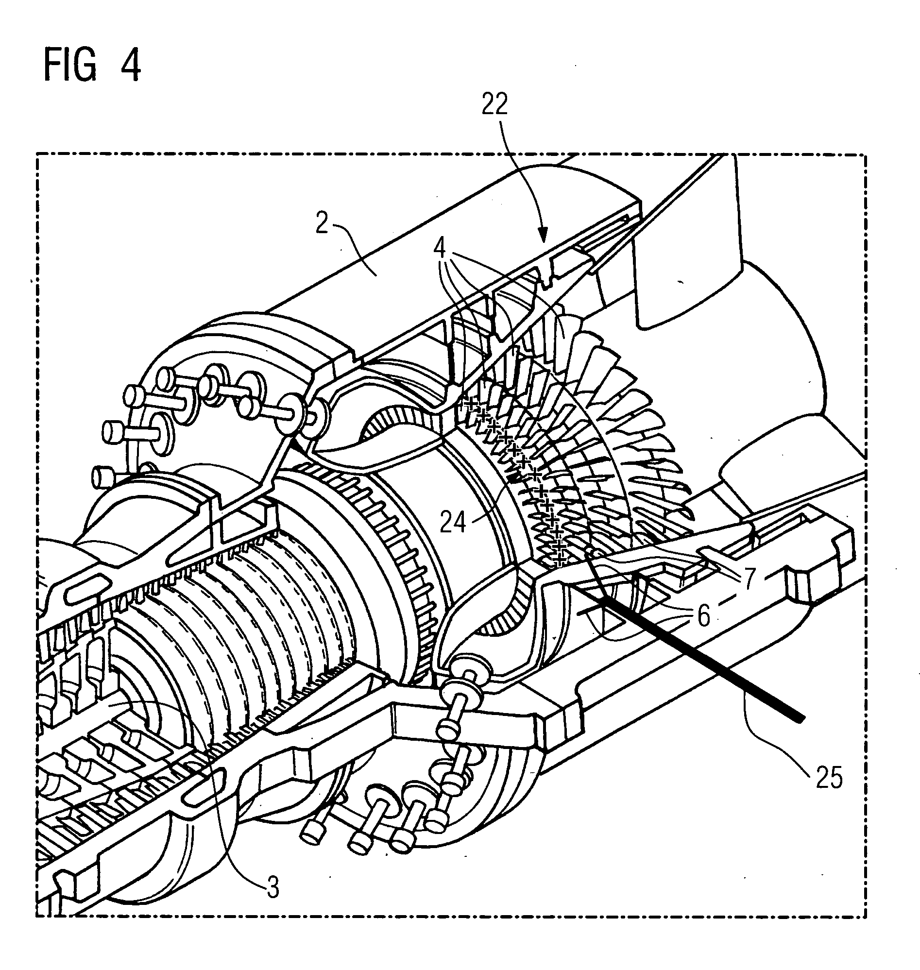
[0039]FIG. 1 shows a perspective view of a gas turbine 1 of the prior art comprising rotor blades 4 arranged on a rotor shaft 3 that is rotatably mounted in a housing 2 and comprising rotationally fixed guide blades 7. An air intake 18 is provided at one axial end, and a compressor 19 arranged axially after it. The compressor 19 is followed by a combustion chamber 20 having burners 21, the turbine area 22 with the gas outlet 23 being connected to this chamber. FIG. 4 shows an enlarged view of the turbine area 22. In FIG. 4, electric charges present on the surface of the rotor blades 4 are labeled with 24.

[0040]FIG. 2 shows an individual rotor blade 4 for arrangement on the rotor shaft 3, made of an electrically conducting material, preferably a metal such as steel or the like. The surface 5 of the rotor blade 4 is provided with an electrically insulating coating, here a ceramic coating.

[0041]FIG. 3 shows a corresponding guide blade 7, also made of an electrically conducting materi...


PUM


Abstract

The turbo engine comprises rotor blades made of an electrically conductive material with an electrically insulating surface, said rotor blades being rotatably mounted on a rotor shaft arranged in a housing. The electrically conductive material of the rotor blades is electrically connected to a reference potential. At least one measuring element is arranged in the area of the rotor blades, said measuring element being intended for measuring an electrical and / or magnetic field strength caused by charge distribution on the surface of the rotor blades.

Description

CROSS REFERENCE TO RELATED APPLICATION [0001] This application is the US National Stage of International Application No. PCT / DE2003 / 003411, filed Oct. 14, 2003 and claims the benefit thereof. The International Application claims the benefits of German Patent application No. 10251720.7 DE filed Nov. 6, 2002, both of the applications are incorporated by reference herein in their entirety.FIELD OF THE INVENTION [0002] The present invention relates to a turbo engine comprising rotor blades made of an electrically conducting material having an electrically insulating surface, said blades being arranged on a rotor shaft that is rotatably mounted in a housing. The invention also relates to a turbo engine comprising rotor blades arranged on a rotor shaft that is rotatably mounted in a housing, and comprising rotationally fixed guide blades made of an electrically conducting material having an electrically insulating surface. BACKGROUND OF THE INVENTION [0003] Turbo engines having blade arra...

Claims


Application Information

Patent Timeline
Patent Type & Authority Applications(United States)
IPC IPC(8): G01R31/06F01D5/28F01D21/00F01D21/14
CPCF01D5/288F05D2260/80F01D21/14F01D21/003
Inventor BOSSELMANN, THOMASEIERMANN, FRANZHEINDEL, HANS-PETERSCHNELL, WILFRIED
Owner SIEMENS AG
Learn More