
Remote control system

a remote control and door lock technology, applied in the field of remote control systems, can solve the problems of reducing the operability of affecting and affecting the operation of the door lock system, so as to facilitate the operability of the portable device and suppress energy consumption

Inactive Publication Date: 2006-01-19
DENSO CORP
View PDF5 Cites 40 Cited by
  • Summary
  • Abstract
  • Description
  • Claims
  • Application Information

AI Technical Summary

Benefits of technology

[0012] It is another object of the present invention to provide a door lock system having an alternative of door lock control features, that is, a feature based on a bi-directional communication between a portable device and a station unit, and a feature base on a user operation on the portable device for transmitting a signal to a station unit, with a reduction of energy consumption by preventing activation of useless operation on the station unit.
[0014] The user having the portable device usually approaches the door for a driver's seat to get into the automobile. Therefore, access to each of the doors of the automobile is different in frequency. Further, the transmitter in each door transmits the request signal in different intervals because of the difference of access to each door. Thus, the transmitter in each door may be controlled to transmit the request signal differently from other transmitters, taking advantage of the difference of access to each door, to reduce energy consumption without sacrificing operability.
[0016] The user of the portable device may approach the door for the driver's seat, the door for a passenger's seat or the door for either of rear seats. The door lock system having the history of use controls each transmitter for responding to the approaching portable device according to the history of use, that is, a frequency of access. The door lock system prevents deterioration of operability by increasing transmission frequency of the request signal when the user approaches the door of frequent access. Further, the energy consumption by the door lock system is decreased by decreasing the frequency of transmitting the request signal from the less frequently used transmitter.
[0020] The door lock system of the present invention may further facilitate the operability of the portable device in the following manner. That is, the portable device may use a first signal and a second signal for controlling the door lock. The portable device transmits the first signal upon receiving the input from the user, and transmits the second signal in response to the request signal from the station unit disposed on the automobile. The station unit intermittently transmits the request signal to the portable device, and intermittently prepares to receive the first signal with a readiness for receiving the second signal in synchronization with the transmission of the request signal. The station unit records use of the first and second signal by the user, and controls the frequency of reception operation for receiving each of the first signal and the second signal. That is, the frequency for receiving the first signal by intermittently turning on the station unit or a reception part of the unit, and the frequency of transmission of the request signal from the station unit accompanied by readiness for receiving the second signal in response to the request signal, are individually controlled based on the recorded use of the signals.
[0021] The door lock system of the present invention uses an above-described scheme of operation to suitably operate the part of the station unit in less frequent use for suppressing energy consumption.

Problems solved by technology

The feature may cause a rundown of the battery when the automobile is parked for an extended period of time.
However, simply using the longer interval for transmitting the request signals may cause a delayed detection of the approaching user.
Delayed detection may cause a decreased operability of the door lock system such as a delay for unlocking the door lock when the user touches on the door handle.
However, the user tends to use only one feature of the door lock system.
Therefore, activating a less-used feature of the door lock system may simply cause inconvenience for the user by, for example, consuming the battery in vain.

Method used


Image

  • Remote control system
  • Remote control system
  • Remote control system

Examples


first embodiment

[0032] the present invention is described with reference to the drawings.

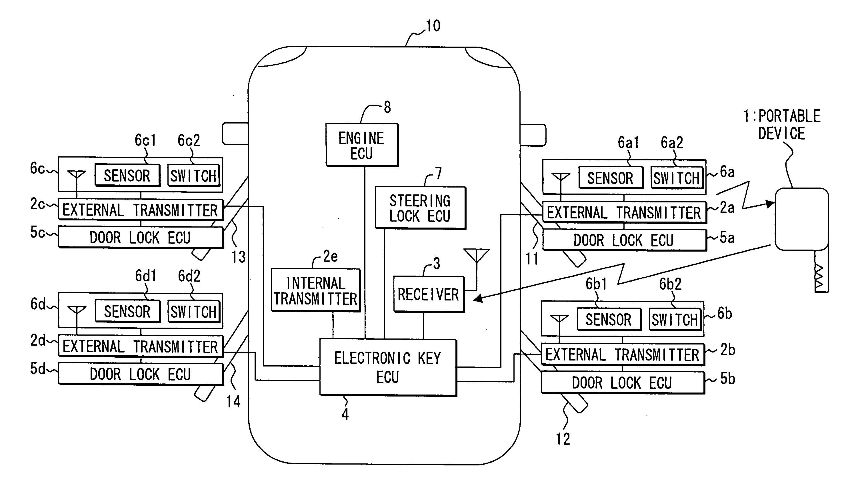
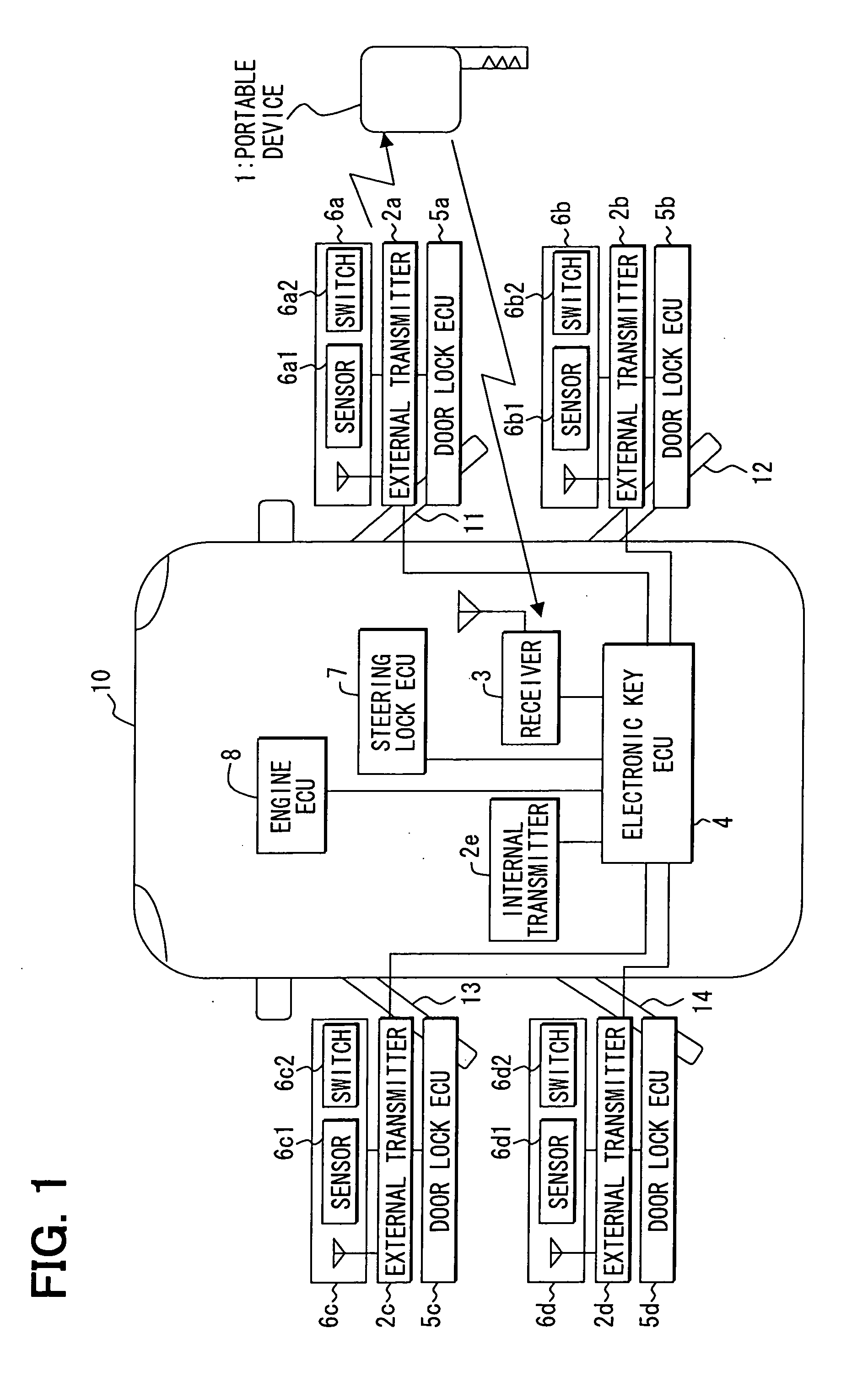
[0033]FIG. 1 shows a block diagram of a door lock system in the first embodiment. The door lock system includes a portable device (an electronic key) 1 and an electronic key ECU 4 to control lock / unlock operation of the door locks in each door based on a bidirectional communication for transmitting an ID code. The electronic key ECU 4 also controls steering lock condition and engine operation for improved security of an automobile 10.

[0034] The door lock system also includes a receiver 3 for receiving signals from the portable device 1 and is electrically connected to a steering lock ECU 7 and an engine ECU 8 as shown in FIG. 1.

[0035] The automobile 10 includes external transmitters 2a to 2d in doors 11 to 14 and an internal transmitter 2e in an inside of the automobile 10. The transmitters 2a to 2e transmit a request signal based on a transmission signal from the electronic key ECU 4. The electronic key ECU ...


PUM


Abstract

A door lock system for controlling access to an automobile includes at least one transmitter in the door of the automobile for transmitting a request signal, a portable device for transmitting a response signal having an ID code in response to the request signal, a receiver for receiving the response signal, and a controller for controlling a lock in the door based on an identity of the ID code. The transmitter and the receiver intermittently operate to respond to a user of the portable device.

Description

CROSS REFERENCE TO RELATED APPLICATION [0001] This application is based on and claims the benefit of priority of Japanese Patent Application No. 2004-207625 filed on Jul. 14, 2004, the disclosure of which is incorporated herein by reference. FIELD OF THE INVENTION [0002] The present invention generally relates to a door lock system, and more specifically to a door lock system having a portable device for controlling a door lock. BACKGROUND OF THE INVENTION [0003] A conventional door lock system uses a portable device for remotely controlling a door lock condition based on a result of identification (ID) code matching through a bidirectional communication between the portable device and a station unit on, for example, an automobile. This type of door lock system sets a detection area for detecting the portable device, and recognizes an approaching portable device by transmitting a request signal to the portable device in a predetermined interval of time. In this manner, the door lock...

Claims


Application Information

Patent Timeline
IPC IPC(8): G05B19/00B60R25/01B60R25/24B60R25/31E05B49/00E05B83/36
CPCB60R25/04B60R25/246B60R25/403G07C2209/65G07C9/00309G07C2009/00388G07C2009/00793G05B19/042
Inventor TESHIMA, KENTAROKATO, YUJI
Owner DENSO CORP
Learn More