Carriage assembly of a hard disk drive and method of manufacturing the same

a hard disk drive and carriage assembly technology, applied in the direction of manufacturing tools, soldering devices, instruments, etc., can solve the problems of reducing the service life of the flying lead, so as to achieve the effect of simplifying the manufacturing process and manufacturing equipmen

Inactive Publication Date: 2006-01-19
KK TOSHIBA
View PDF2 Cites 7 Cited by
  • Summary
  • Abstract
  • Description
  • Claims
  • Application Information

AI Technical Summary

Benefits of technology

[0034] By doing so, since the ultrasonic tool used to bond the flying leads and the bonding terminals together is heated as it is, there is no need to provide a heating means or the like that is separate to the ultrasonic tool and heats the coating layer, which means that the manufacturing process and manufacturing equipment can be simplified.
[0035] Another method according to the present invention is a method of manufacturing a cartridge assembly of a hard disk drive according to any of Claim 1 to Claim 3, including: a step of placing an ultrasonic tool in contact with the opposite surfaces of the flying leads and ultrasonically bonding the flying leads and the bonding terminals together by applying ultrasonic vibration from the ultrasonic tool in a state where the flying leads are pressed onto the bonding terminals; and a step of covering the respective opposite surfaces of the flying leads that have been roughened by contact with the ultrasonic tool during the ultrasonic bonding with the thermally meltable metal that has been heated and melted to form the respective coating layers and thereby make the respective opposite surfaces smooth.
[0036] According to the present invention, coating layers (thermally meltable metal) formed on the respective opposite surfaces of the flying leads to the surfaces bonded to the bonding terminals are heated to make the surfaces that contact the ultrasonic tool smooth. Accordingly, it is possible, without applying a resin coating onto the flying leads that would span the flexible printed circuit board and the bonding terminals, to eradicate the roughness of the surfaces of the flying leads that contact the ultrasonic tool and would otherwise produce dust.

Problems solved by technology

This means that there are cases where the application of a large force to the flying leads 15a causes the flying leads 15a to break, resulting in the problem that replacement becomes difficult or no longer possible.
Also, even if the flying leads 15a do not break, residue of the resin coating that is deposited on the bonding terminals 16a gets in the way, resulting in the problem that rebonding of the flying leads 15a becomes difficult or no longer possible.

Method used


Image

  • Carriage assembly of a hard disk drive and method of manufacturing the same
  • Carriage assembly of a hard disk drive and method of manufacturing the same
  • Carriage assembly of a hard disk drive and method of manufacturing the same

Examples


Embodiment Construction

[0047] Preferred embodiments of the present invention will now be described with reference to the enclosed drawings.

[0048] It should be noted that parts that are the same as in the conventional carriage assembly have been assigned the same reference numerals and description of such has been omitted.

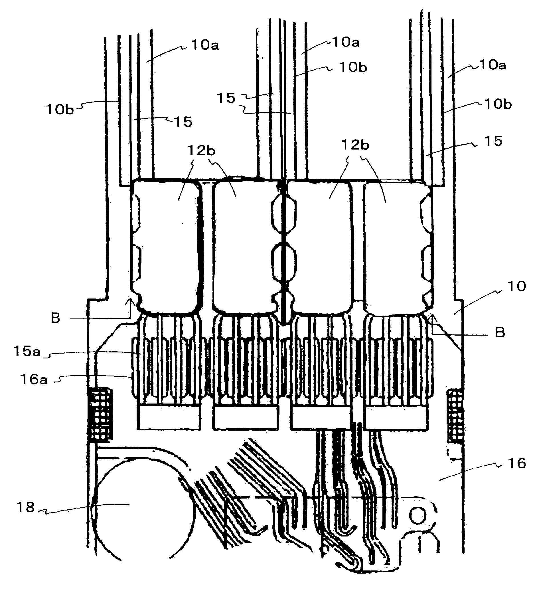
[0049] The external appearance and fundamental construction of a carriage assembly according to the present invention and a long tail suspension circuit board of this carriage assembly are the same as the carriage assembly C and the long tail suspension circuit board 12 shown in FIGS. 3 to 5, and therefore description of such has been omitted.

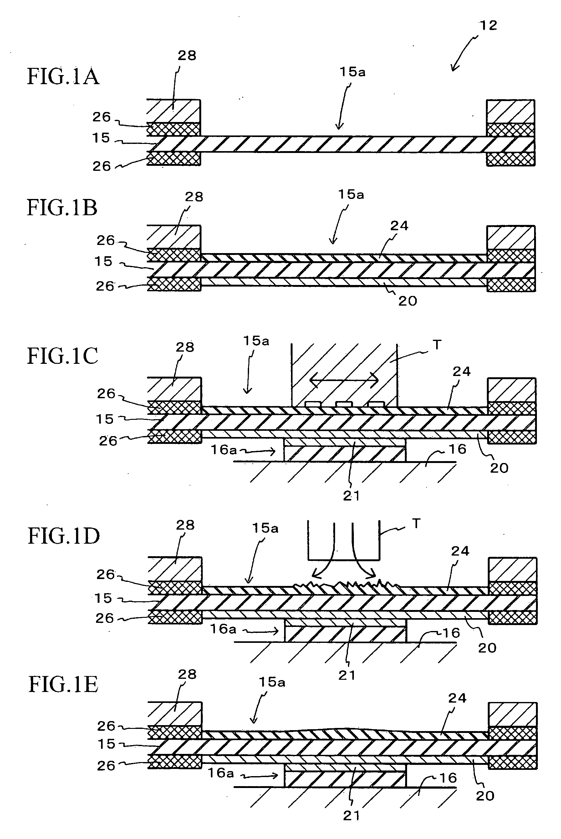
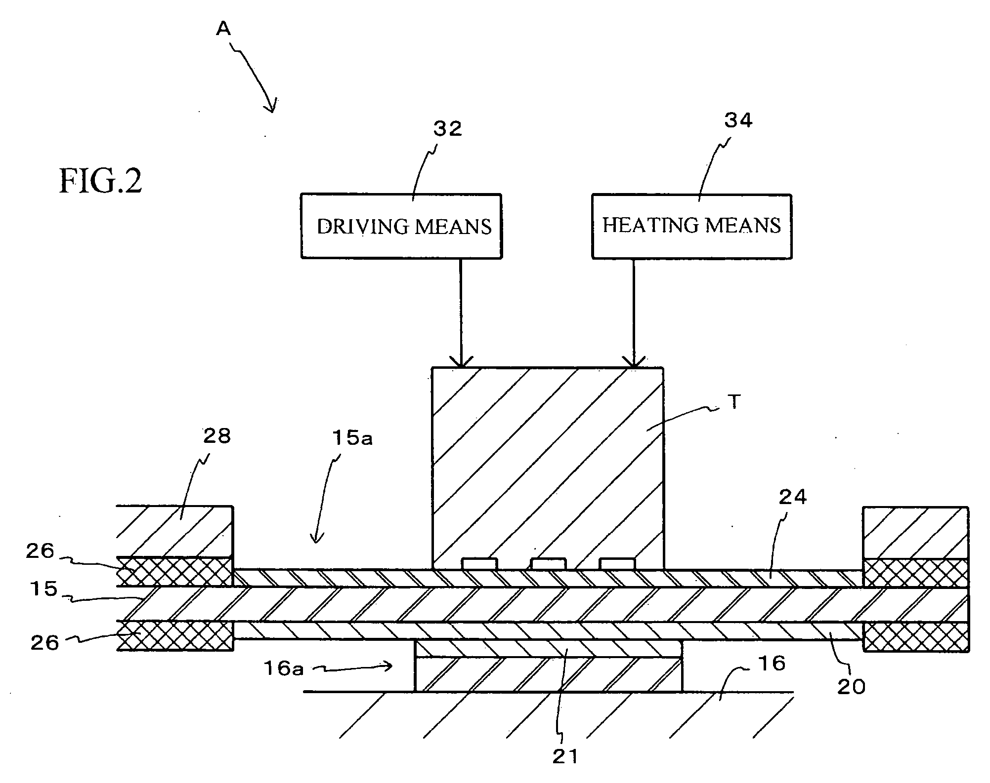
[0050] The carriage assembly C according to the present invention is characterized by the construction of the flying leads 15a of the long tail suspension circuit board 12.

[0051]FIGS. 1A to 1E are a series of diagrams useful in explaining the carriage assembly C according to the present invention and a method of manufacturing the same, and are cr...


PUM

PropertyMeasurementUnit
flexibleaaaaaaaaaa
temperatureaaaaaaaaaa
recording densityaaaaaaaaaa

Abstract

A carriage assembly of a hard disk drive, and a manufacturing apparatus for the same are not susceptible to problems such as flying leads breaking and resin residue being deposited on bonding terminals when the flying leads of a long tail suspension circuit board are pulled off the bonding terminals of a flexible printed circuit board. The flying leads of the long tail suspension circuit board and the bonding terminals of the flexible printed circuit board are ultrasonically bonded together by placing an ultrasonic tool in contact with opposite surfaces of the flying leads to the surfaces that are bonded to the bonding terminals and applying ultrasonic vibration from the ultrasonic tool in a state where the flying leads are pressed onto the bonding terminals. Coating layers composed of a thermally meltable metal that melts at a lower temperature than the material forming the bonding surfaces are respectively formed on the opposite surfaces of the flying leads.

Description

BACKGROUND OF THE INVENTION [0001] 1. Field of the Invention [0002] The present invention relates to a carriage assembly of a hard disk drive which is provided with a wiring circuit electrically connected to a magnetic head and includes a long tail suspension circuit board where part of the wiring circuit is formed as flying leads and a flexible printed circuit board on which bonding terminals to which the flying leads are bonded are provided, and to a method of manufacturing the carriage assembly. [0003] 2. Related Art [0004] In recent years, in the field of hard disk drives (magnetic disk apparatuses), as the recording density of magnetic disks has increased and access speeds have become faster, the construction of a carriage assembly, and in particular the constructions of the suspension and flexible printed circuit board have been rationalized. [0005] More specifically, “suspension circuit boards”, where a wiring circuit is formed in advance on the surface or another part of the...

Claims


Application Information

Patent Timeline
Patent Type & Authority Applications(United States)
IPC IPC(8): G11B5/48
CPCG11B5/4833G11B5/4846G11B5/486H05K1/056H05K3/363Y10T29/49027H05K2201/0969H05K2203/0285Y10T29/49025Y10T29/4903H05K2201/0394
Inventor KOBAE, KENJIKUBOTA, TAKASHI
Owner KK TOSHIBA
Why Eureka
Try Eureka