Audio signal output circuit and electronic apparatus outputting audio signal

a technology of audio signal and output circuit, which is applied in the direction of electrical transducers, transducer casings/cabinets/supports, gain control, etc., can solve problems such as circuit construction, and achieve the effect of preventing pop nois

Inactive Publication Date: 2006-01-19
ROHM CO LTD
View PDF5 Cites 46 Cited by
  • Summary
  • Abstract
  • Description
  • Claims
  • Application Information

AI Technical Summary

Benefits of technology

[0005] It is, therefore, an object of the present invention to provide a digital audio signal output circuit capable of preventing pop noise from occurring, without using any analog circuit or mute control signal for external devices.

Problems solved by technology

Thus, the prior art circuit as disclosed in Document 1 disadvantageously requires many such components as coupling capacitor and changeover switch in a later stage of the audio signal output circuit, in addition to a mute signal generator for controlling the switch, which is a drawback in constructing the circuit in the form of an IC.

Method used


Image

  • Audio signal output circuit and electronic apparatus outputting audio signal
  • Audio signal output circuit and electronic apparatus outputting audio signal
  • Audio signal output circuit and electronic apparatus outputting audio signal

Examples


first embodiment

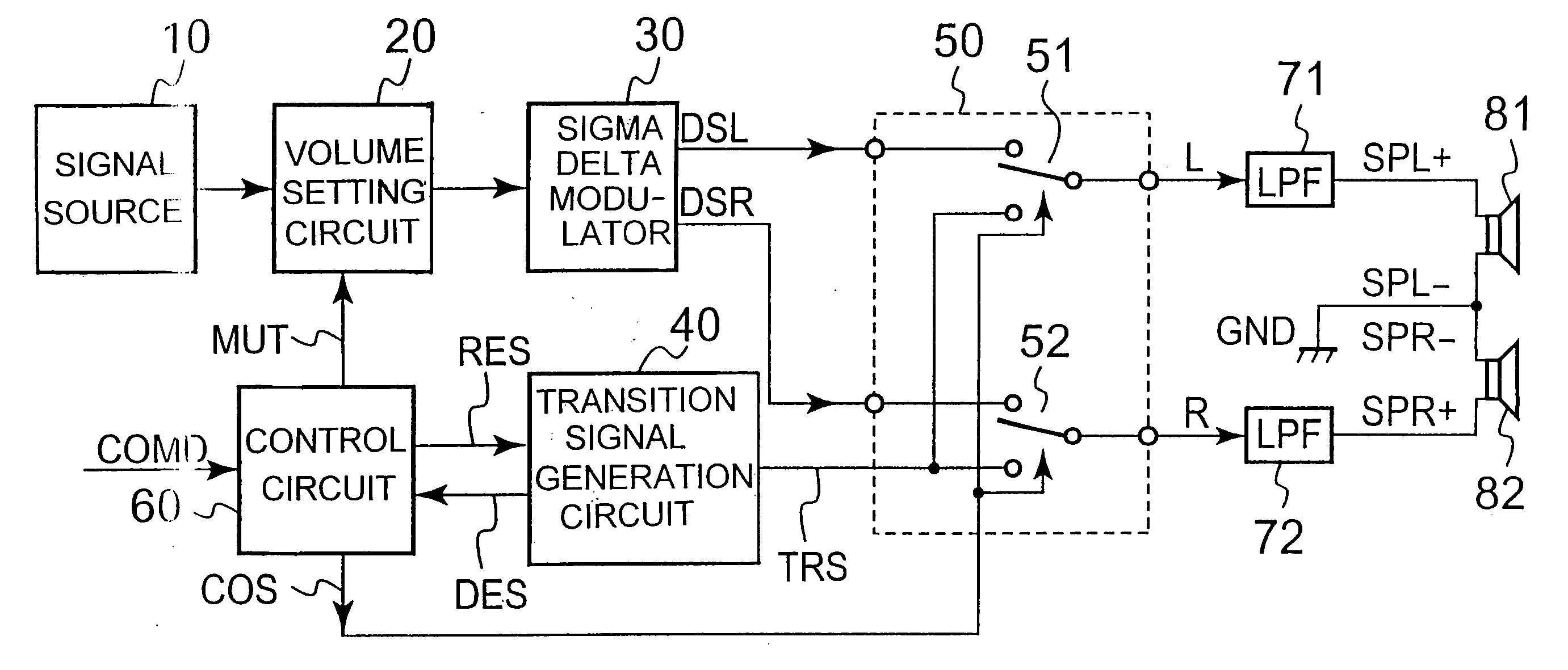
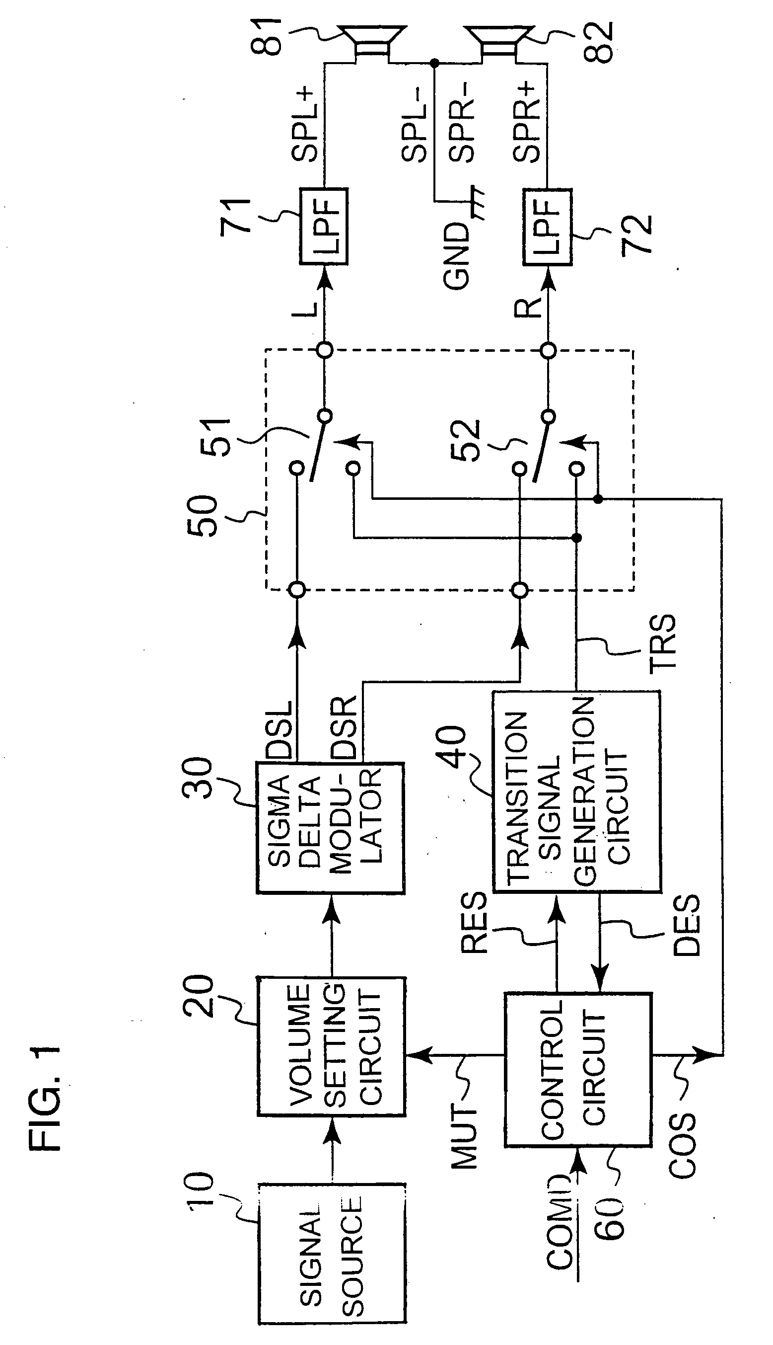
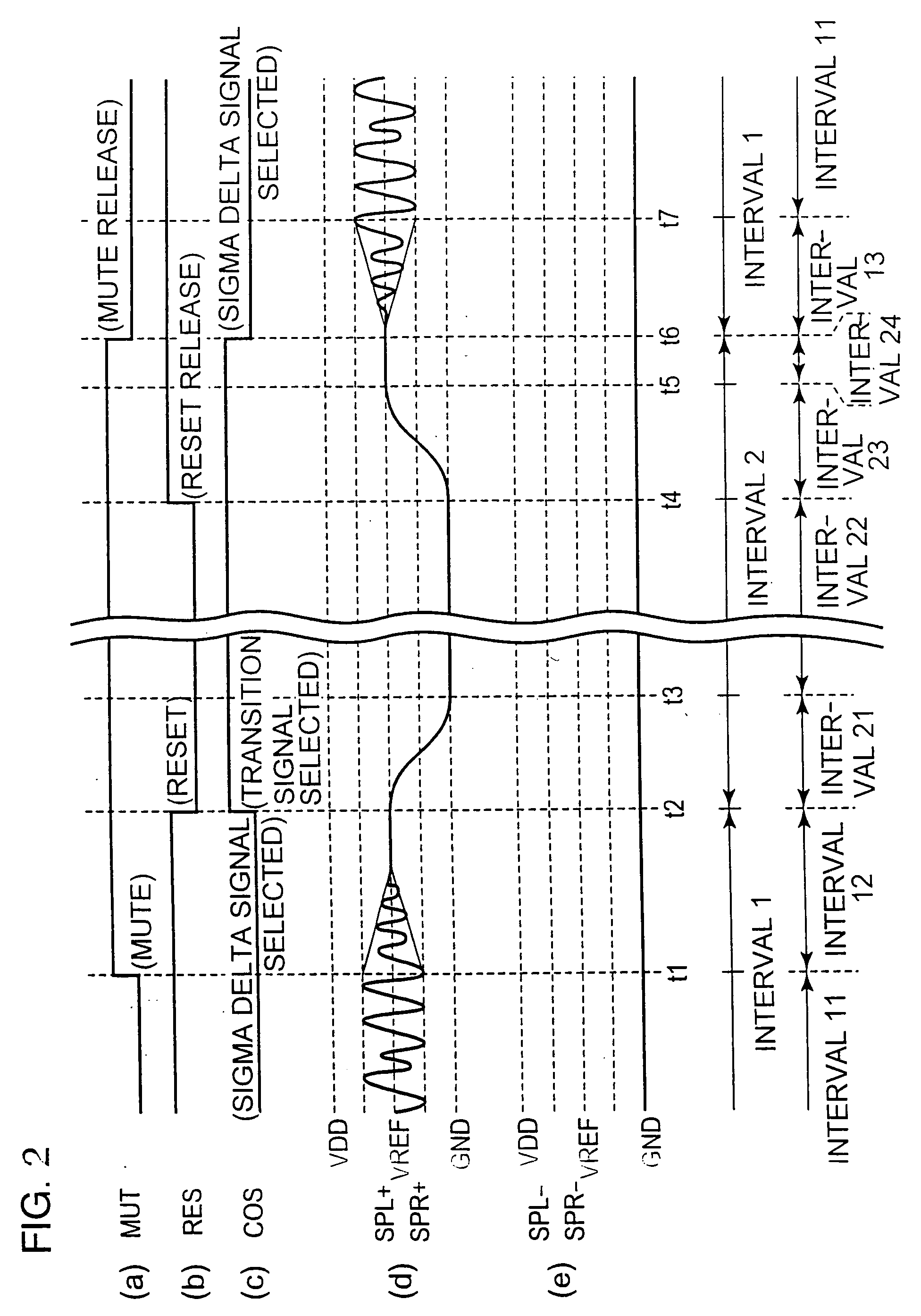
[0078] Referring to FIG. 1, there is shown an audio signal output circuit according to the invention, along with an arrangement of an electronic apparatus utilizing the circuit. FIG. 2 is a timing diagram illustrating operation of the audio signal output circuit shown in FIG. 1.

[0079] As seen in FIG. 1, an audio signal having an AC component is fed from a signal source 10 to a volume setting circuit 20, the AC component being indicative of voice and superposed on a DC component (referred to as reference voltage VREF) of the input audio signal. This audio signal is a multi-bit (e.g., 16-bit) digital signal. The reference voltage VREF is between a given power supply voltage VDD and the ground voltage GND, preferably an intermediate voltage between the two voltages. The signal source 10 may be provided either within or outside the audio signal output circuit. It should be understood that in what follows voltages are taken with respect to the ground potential GND unless otherwise stated...

second embodiment

[0111] Referring to FIG. 5, there is shown an arrangement of an audio signal output circuit according to the invention, along with an electronic apparatus utilizing the output circuit. FIG. 6 is a timing diagram illustrating operation of the circuit shown in FIG. 5.

[0112] The second embodiment has substantially the same power-off and power-on sequences as the first embodiment shown in FIGS. 1 and 2. The second embodiment differs from the first in that the speakers (loads) are driven in a differential voltage scheme, and, the differential signals are supplied to the loads out of phase by 180 degrees when the loads are driven by delta sigma signals, while transition signal is supplied to the loads in phase when stopping the loads.

[0113] The signal source 10, volume setting circuit 20, delta sigma modulator 30, transition signal generation circuit 40, and control circuit 60 of FIG. 5 are the same as the elements having the same reference numerals in FIG. 1.

[0114] An inverted signal g...

third embodiment

[0133] Referring to FIG. 7, there is shown an audio signal output circuit according to the invention along with an electronic apparatus utilizing the output circuit. FIG. 8 is a timing diagram illustrating operation of the circuit shown in FIG. 7.

[0134] In the third embodiment shown, power-off and power-on sequences of the audio signal output circuit are substantially the same as those of the first embodiment shown in FIGS. 1 and 2, and of the second embodiment shown in FIGS. 5 and 6. The third embodiment differs from the first and second embodiments in that, when the circuit is in the audio signal output mode outputting an audio signal to the loads (speakers 81 and 82), the first and second audio signals are supplied to respective one end of the speaker 81 and of speaker 82 while the transition signal TRS is supplied to the other ends of the respective speakers 81 and 82, and that the transition signal TRS is supplied in phase to the both ends of each speaker 81 and 82 when the aud...


PUM


Abstract

A digital audio-signal output circuit is provided, which is capable of outputting an audio signal without generating pop noise. In suppressing pop noise, the audio signal output circuit requires no analog circuit nor mute control signal for external peripheral devices. Upon receipt of a digital input audio signal having an AC component superposed on a reference voltage VREF, the circuit selects one of a pulse-density-modulated audio signal derived from the input audio signal and a transition signal that smoothly varies between zero volt and the reference voltage, and provides the selected signal to speakers.

Description

FIELD OF THE INVENTION [0001] This invention relates to an audio signal output circuit capable of outputting audio signal with suppressed “pop” noise (or pop sound) generated at the power-on and -off of the circuit, and to an electronic apparatus utilizing such audio signal output circuit. BACKGROUND OF THE INVENTION [0002] There have been disclosed a variety of audio signal output circuits adapted to prevent generation of pop noise that occurs at the time of power-on and power-off of an audio output amplifier. [0003] For example, Japanese Patent Application Laid Open No. 2003-258559 (referred to as Document 1) discloses a circuit having a drive amplifier, a coupling capacitor, and a changeover switch for switching the connection of the coupling capacitor to a speaker or to the ground in response to a mute signal received. As a consequence, the signal-flow path to the speaker is shut down and at the same time the coupling capacitor is rapidly charged or discharged to prevent pop noi...

Claims


Application Information

Patent Timeline
Patent Type & Authority Applications(United States)
IPC IPC(8): H03G3/00H04B15/00
CPCH03G3/348
Inventor SAKAIDANI, SATOSHI
Owner ROHM CO LTD
Why Eureka
Try Eureka