
Method and apparatus for processing image data

a technology for image data and processing methods, applied in image analysis, instruments, computing, etc., can solve the problems of requiring a substantial amount of storage space, unable to eliminate the need for vcr, and relatively complex and expensive components, so as to achieve a small image stream and reduce the size of compressed data

Inactive Publication Date: 2006-01-19
VISLOG TECH PTE +1
View PDF2 Cites 110 Cited by
  • Summary
  • Abstract
  • Description
  • Claims
  • Application Information

AI Technical Summary

Benefits of technology

[0021] In the described embodiment a video encoding scheme for a network surveillance camera is provided that addresses the bit rate and foreground / background segmentation problems of the prior art. All the important image details can be kept during encoding and transmission processes and the compressed data size can be kept low. The proposed video encoding scheme identifies all the stationary objects in the scene (such as door, wall, window, table, chair, computer, and etc.) as background regions and all the moving objects (people, animal, and etc.) as foreground regions. After separating the image frames into foreground regions and background regions, the video encoding scheme sends background data in low frequency and foreground data in high frequency. If the number of images captured by a network camera in each second is 25, the total number of frames captured will be 30×60×25=45000 for 30 minutes. If each image has a size of 50 kbyte (after JPEG compression), the total size will be 2.25 Gbyte. In an indoor room environment, however, the room may be empty at most of the time. Assuming that out of 30 minutes, the time people are moving in the room is 10 minutes and the area occupied by the moving people is one eighth of the whole image area. By using the proposed foreground / background separation and transmission scheme, the total data can be further compressed to a much smaller size of 93.8 Mbyte. Thus, the network camera of the described embodiment of the present invention is able to produce a much smaller image stream of the same quality when compared with a traditional network camera. In the example given above, the size of image data generated by a network camera of the described embodiment of the present invention is only one twenty fourth of that of a traditional network camera. By separating foreground-moving objects from background, the described embodiment has another advantage over the traditional network camera: high-level information such as size, color, classification, or moving directions of foreground objects can be easily extracted from the foreground objects and used in video indexing or intelligent camera applications.

Problems solved by technology

However, it does not eliminate the need for the VCR, which is a relatively complex and expensive component that is subject to mechanical failure, frequent tape cassette change, and periodic maintenance, such as cleaning of the video heads.
This category is relatively expensive.
It requires a substantial amount of storage space.
The disadvantages of this category include: lack of flexibility, heavy cabling work, and high cost.
The installation is not necessarily permanent since the cameras can easily be moved around a building.
Such a transmission speed is not acceptable in surveillance applications.
This is feasible in media production applications but is absolutely impossible in a surveillance application.
The method of this patent cannot be used in foreground / background separation for surveillance applications.
All of these known approaches have been generally adequate for their intended purposes, but they are not satisfactory in surveillance network camera applications.
Although some of the network cameras use image analysis techniques to perform motion detection, none of them is capable of background / foreground separation, encoding, and transmission.

Method used


Image

  • Method and apparatus for processing image data
  • Method and apparatus for processing image data
  • Method and apparatus for processing image data

Examples


Embodiment Construction

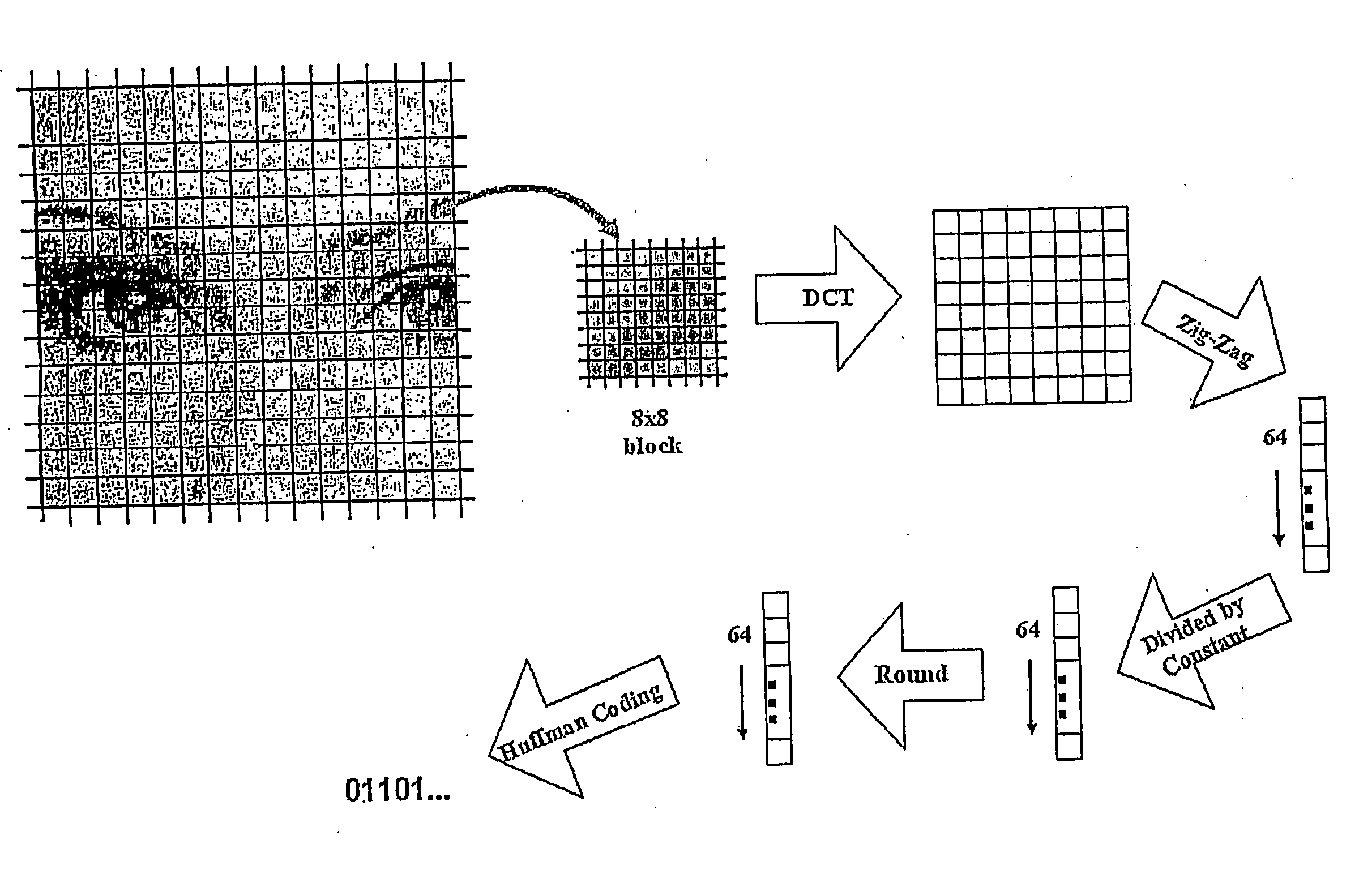
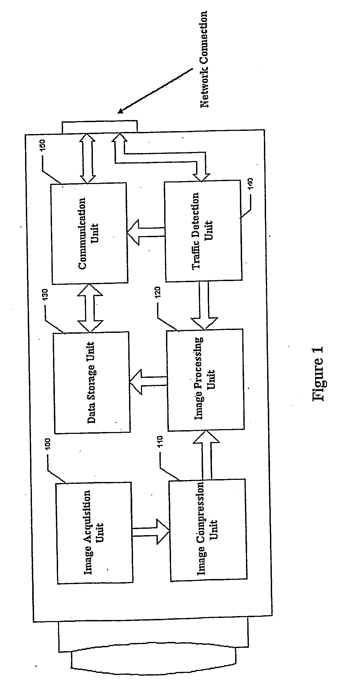
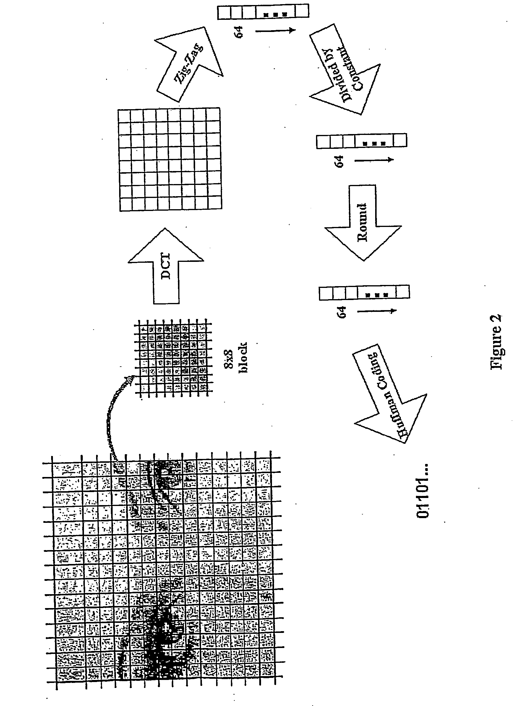
[0035]FIG. 1 is a block diagram of a network camera which embodies the present invention. The network camera includes an image acquisition unit 100, an image compression unit 110, an image processing unit 120, a data storage unit 130, a traffic detection unit 140, and a communication unit 150. The network camera in the disclosed embodiment can be a monochrome camera, color camera, or some other type of camera which will produce two-dimensional images—such as an infrared camera. The image requisition unit 100 of FIG. 1 consists of a CCD or CMOS image sensor device which converts optical signals into electrical signals, and a AID converter which digitizes the analog signal and converts it into a digital image format. The network camera can accept a wide range of bits per pixel, including the use of colour information. The image compression unit 110 of FIG. 1 can be a software program or a circuit—which is commonly found in network cameras on the market The operation of the image compr...


PUM


Abstract

A network camera apparatus is disclosed including an image requisition unit which obtains an analog signal of an image and converts this into digital format; an image compression unit which utilizes standard image compression techniques (JPEG, MJPEG) to decrease the data size; an image processing unit which analyzes the compressed data of each image, detects motion from compressed data, and identifies background and foreground regions for each image; a data storage unit which stores the image data processed by the image processing unit; a traffic detection unit which detects the traffic amount of the network and decides the frame rates of the image data to be transmitted; and a communication unit which communicates with the network to transmit the image data and other signals.

Description

[0001] This application is a continuation of pending U.S. patent application Ser. No. 10 / 483,992, filed Jan. 23, 2004, which is a National Stage Application of PCT / SG01 / 00158, filed Jul. 25, 2001, the disclosures of which are expressly incorporated herein by reference in their entireties.FIELD OF THE INVENTION [0002] The present invention generally relates to a method and apparatus for processing image data, more particularly but not exclusively for a surveillance application. BACKGROUND OF THE INVENTION [0003] Video surveillance cameras are normally used to monitor premises for security purposes. A typical video surveillance system usually involves taking video signals of site activity from one or more video cameras, transmitting the video signals to a remote central monitoring point, and displaying the video signals on video screens for monitoring by security personnel. In some cases where evidentiary support is desired for investigation or where “real-time” human monitoring is im...

Claims


Application Information

Patent Timeline
IPC IPC(8): G06K9/46G06T7/20G06T9/00G06V10/28
CPCG06K9/38G06T7/2053G06T9/00G06T9/007H04N19/176H04N19/59H04N19/136H04N19/137H04N19/164H04N19/17H04N19/115G06T7/254G06V10/28
Inventor DUAN, LING YUZHOU, RUOWEITANG, JUEL HOIGUO, CHUN BIAOQUIAN, GUO YUZHAO, LEI
Owner VISLOG TECH PTE
Learn More