Sleeve bearing for railway traction motor

a technology traction motor, which is applied in the direction of crankshaft mounting, transportation and packaging, axle box mounting, etc., can solve the problems of limited load rating of pinion-end sleeve bearing, and achieve the effect of extending the wetted area available envelop

Active Publication Date: 2006-01-19
MAGNUS
View PDF12 Cites 16 Cited by
  • Summary
  • Abstract
  • Description
  • Claims
  • Application Information

AI Technical Summary

Benefits of technology

[0007] According to the present invention, the sleeve bearing is provided with the ability to provide additional lubrication to the lateral areas beyond the width of the main supply wick by the addition of additional wicks one on either axial side of the central wick or by incorporating passageways near the 6:00 location on either axial side capable of communicating with the oil accumulated in the oil flinger grooves and taking advantage of the oil-flinger rotating lift capability and lateral movement within the bearing lateral clearances for providing additional lubrication and for extending the envelope of the wetted area available for supporting the truck-axle journal in the axial direction.

Problems solved by technology

Pinion-end sleeve bearing load ratings are frequently limited by the axial length that can be reliably lubricated by the lubrication delivery system.

Method used


Image

  • Sleeve bearing for railway traction motor
  • Sleeve bearing for railway traction motor
  • Sleeve bearing for railway traction motor

Examples


Embodiment Construction

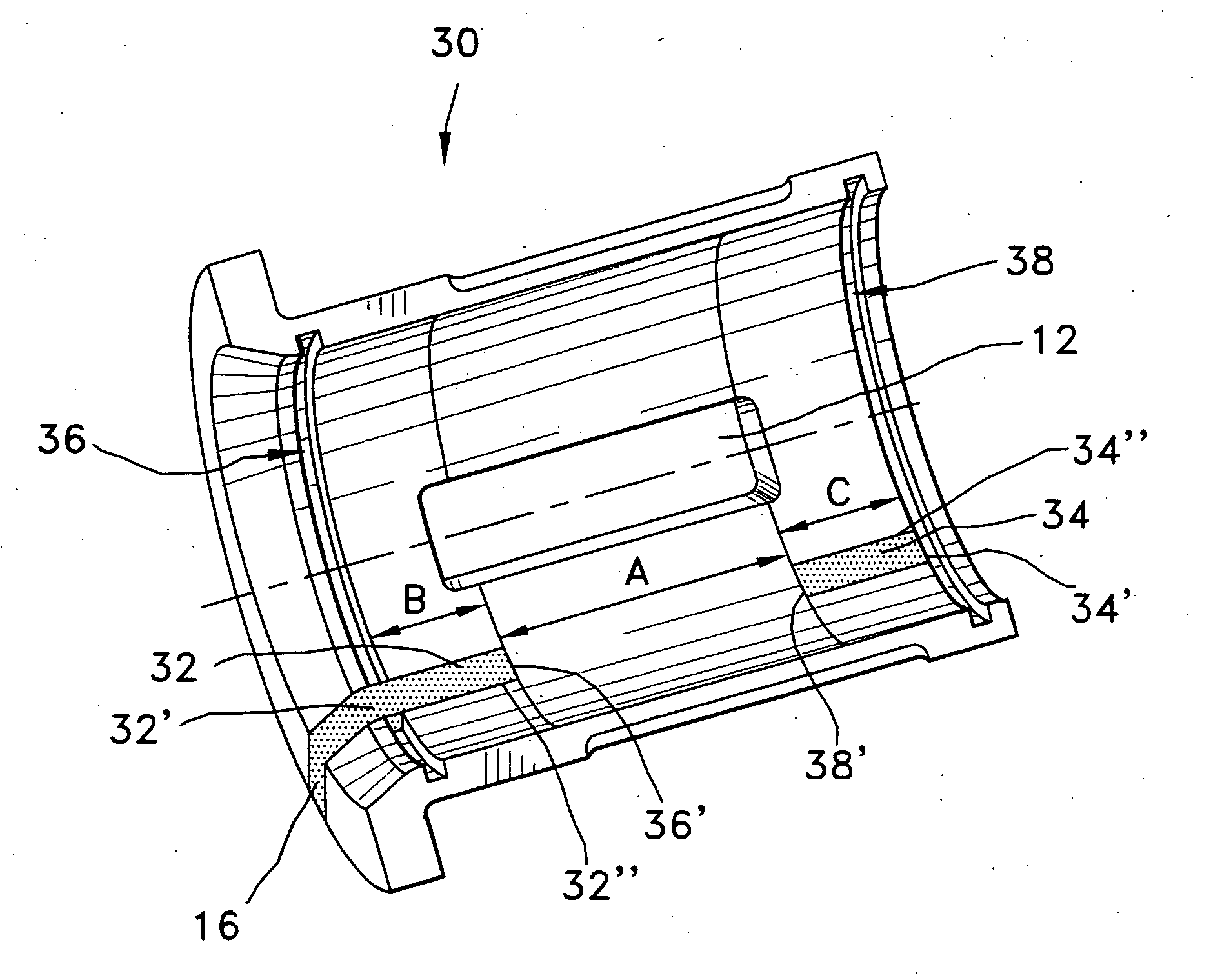
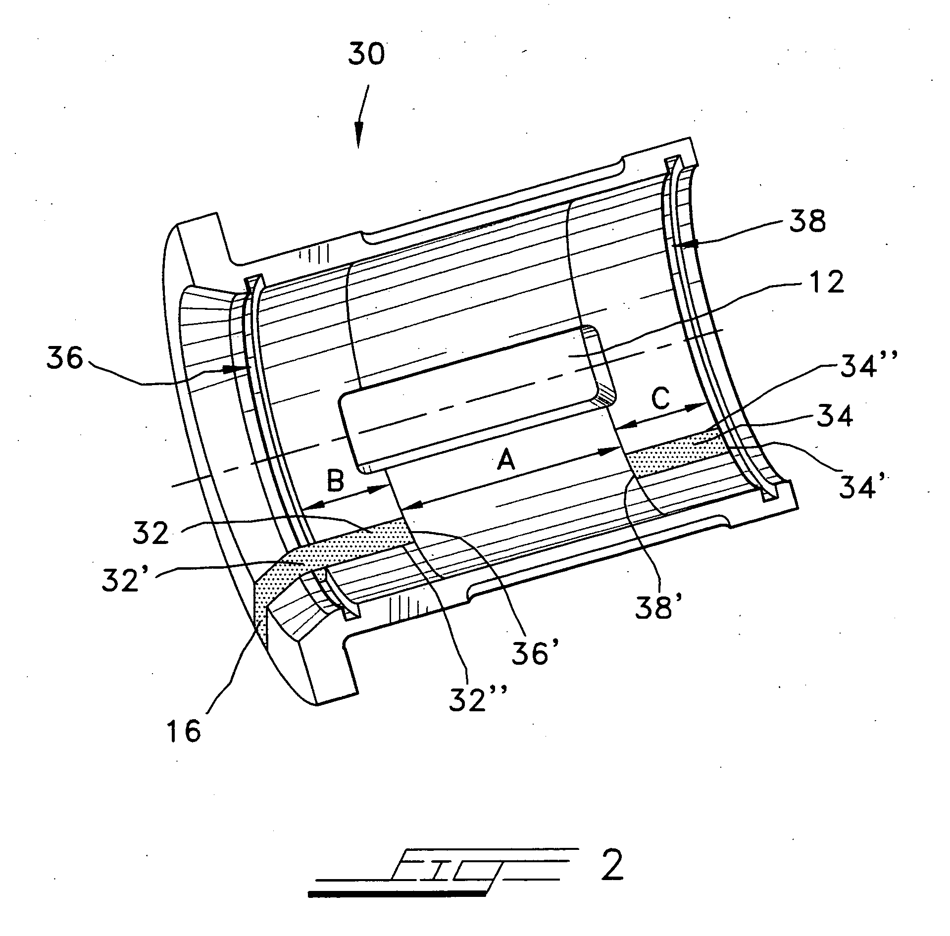
[0018] Referring now to the drawings in greater detail, and to FIGS. 2 and 5 for now, there is shown a first embodiment of the railway-locomotive traction motor friction support or sleeve bearing of the invention and indicated generally by reference numeral 30. In this first embodiment, the invention is embodied in a friction support bearing that does not employ flinger grooves. Flinger grooves mount flinger rings which, when employed, help to redistribute the oil back to the oil reservoir and reduce oil, loss, as disclosed in U.S. Pat. No. 3,905,659. The sleeve bearing 30 is provided with a conventional central wick window 12, as explained hereinabove with regard to FIGS. 1 and 4, and, in addition, at least two supplemental or auxiliary wicks, one wick 32 at the outboard end and one wick 34 at the inboard end. The supplemental wicks 32, 34 are oriented at 6:00 O'clock when viewing FIG. 2. The outboard wick 32 is combined with the currently-used flange wick 16, also explained above ...


PUM


Abstract

An improved sleeve bearing for locomotive traction motor that provides additional lubrication over and above that of the one central wick currently used. The sleeve bearing is provided with a recirculation system comprised of either at least two additional wicks located near the 6:00 operating location or multiple oil communication and delivery grooves passageways communicating with the oil flinger grooves placed for the purpose of collecting and providing a mechanism for providing additional lubrication for extending the oil-wetted envelope available for supporting the truck-axle journal in the axial direction.

Description

BACKGROUND OF THE INVENTION [0001] The present invention is directed to a railway locomotive traction motor and, in particular, to the friction support or sleeve bearing by which the traction motor is partially supported on the axle of the railway truck mounting the underside of the locomotive, and, in particular, the invention is directed to providing additional lubrication. [0002] A conventional railway locomotive pinion-end (PE) traction-motor support bearing, such as that disclosed in U.S. Pat. No. 5,038,631, is shown in FIGS. 1 and 4, which FIGS. 1 and 4 show the half of the support bearing 10 that contains the window 12 for passing a lubricating wick. For best overall performance and life of the traction-motor support bearing, the load zones for loading the truck axle should be centered. This is so in order that the lubricating wick (not shown) entering the interior of the bearing via the wick window or opening 12 lubricates all contacting surface-areas, which lubricating wick...

Claims


Application Information

Patent Timeline
Patent Type & Authority Applications(United States)
IPC IPC(8): F16C33/02F16C33/24F16C1/00F16C1/24F16C3/14F16C5/00F16C33/10F16C33/16
CPCF16C33/1065F16C33/103
Inventor FOSTER, ROBERT B.BIEN, PAULMACKLIN, JOHN E.
Owner MAGNUS
Why Eureka
Try Eureka