Optoelectronic module

Inactive Publication Date: 2006-01-19
EZCONN
View PDF7 Cites 25 Cited by
  • Summary
  • Abstract
  • Description
  • Claims
  • Application Information

AI Technical Summary

Benefits of technology

[0014] An arrangement for data transfer is provided in which good screening between the submodules, in particular between the transmitting module and the receiving module, is present and a compact construction is nevertheless provided, in particular also for an SFF design or an SFP design. The good screening between the submodules also enables use for passive optical networks. Partial recourse to standard submodules furthermore enables the module acco

Problems solved by technology

It is disadvantageous that modules of this type are too large to be used in SFF or SFP transceiver modules.
What is disadvantageous, however, is that the optoelectronic performance of such bidirectional assemblies is not outstanding.
What is

Method used


Image

  • Optoelectronic module
  • Optoelectronic module
  • Optoelectronic module

Examples


Embodiment Construction

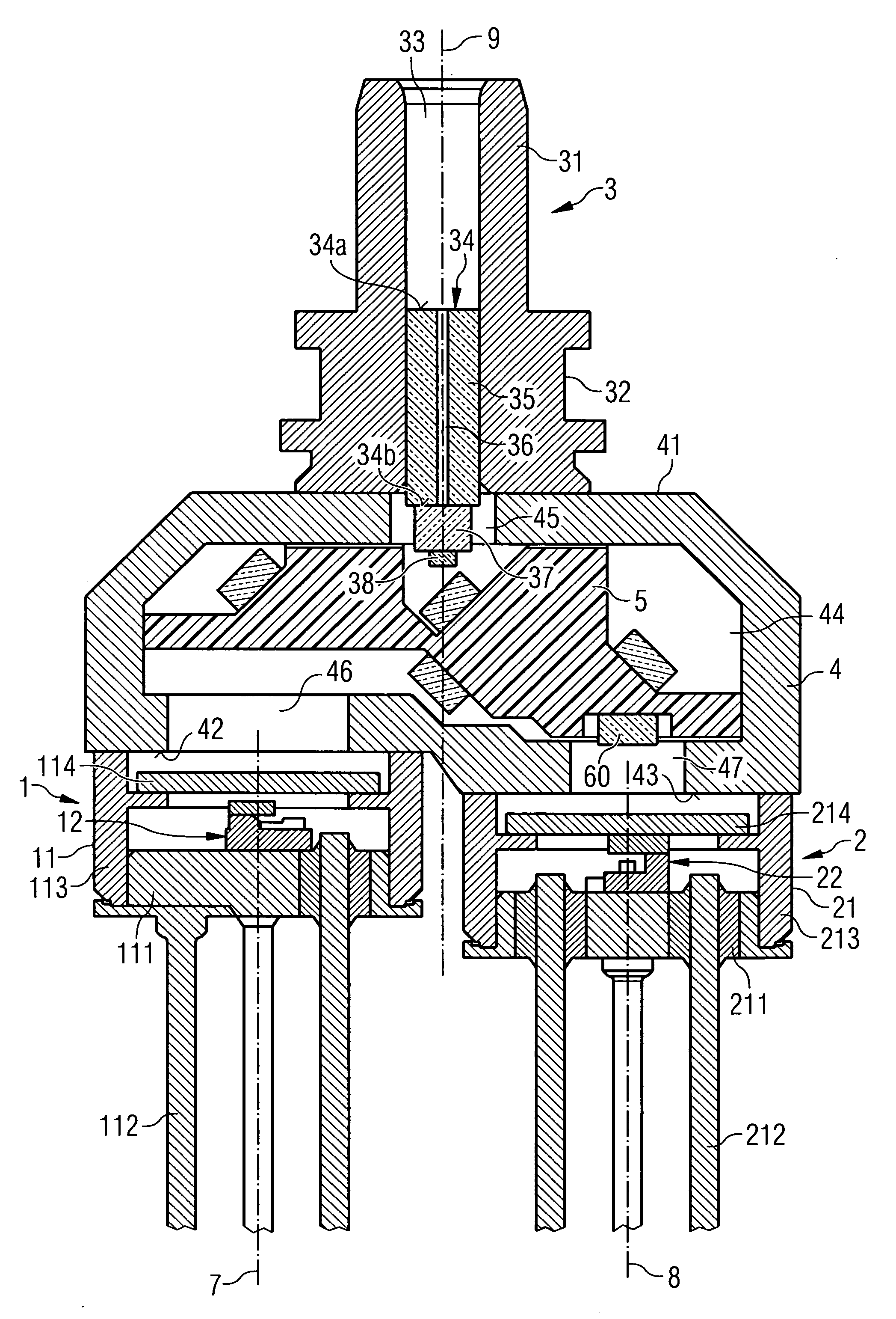
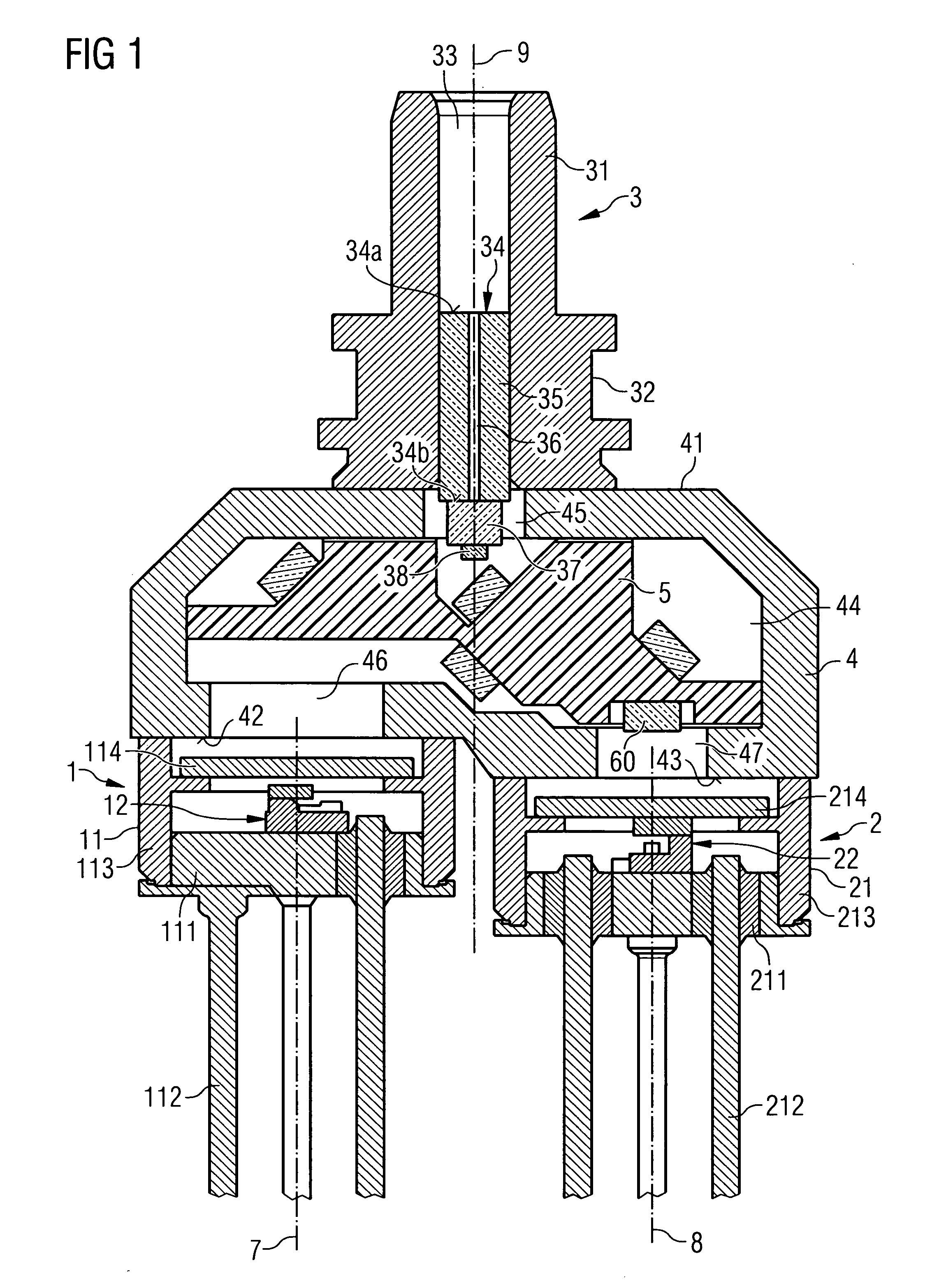
[0040] The optoelectronic device for bidirectional data transfer as illustrated in FIGS. 1 to 6 has, as essential components, a transmitting module 1, a receiving module 2, a coupling device 3—also referred to as receptacle—for coupling an optical waveguide, a housing 4 and a beam splitting device 5.

[0041] The transmitting module 1 and the receiving module 2 are in each case formed in a TO design. A TO46 design is preferably used. The transmitting module 1 comprises a TO housing 11 and a transmitting assembly 12. The TO housing has a TO baseplate 111 (also referred to as TO header), into which housing pins 112 for electrically linking the module are introduced, and a metallic cap 113 with a glazed window 114. In this case, the metallic cap 113 is not a standard cap: it has a weldable area at its end facing the housing 4. The 113 is welded onto the baseplate 111.

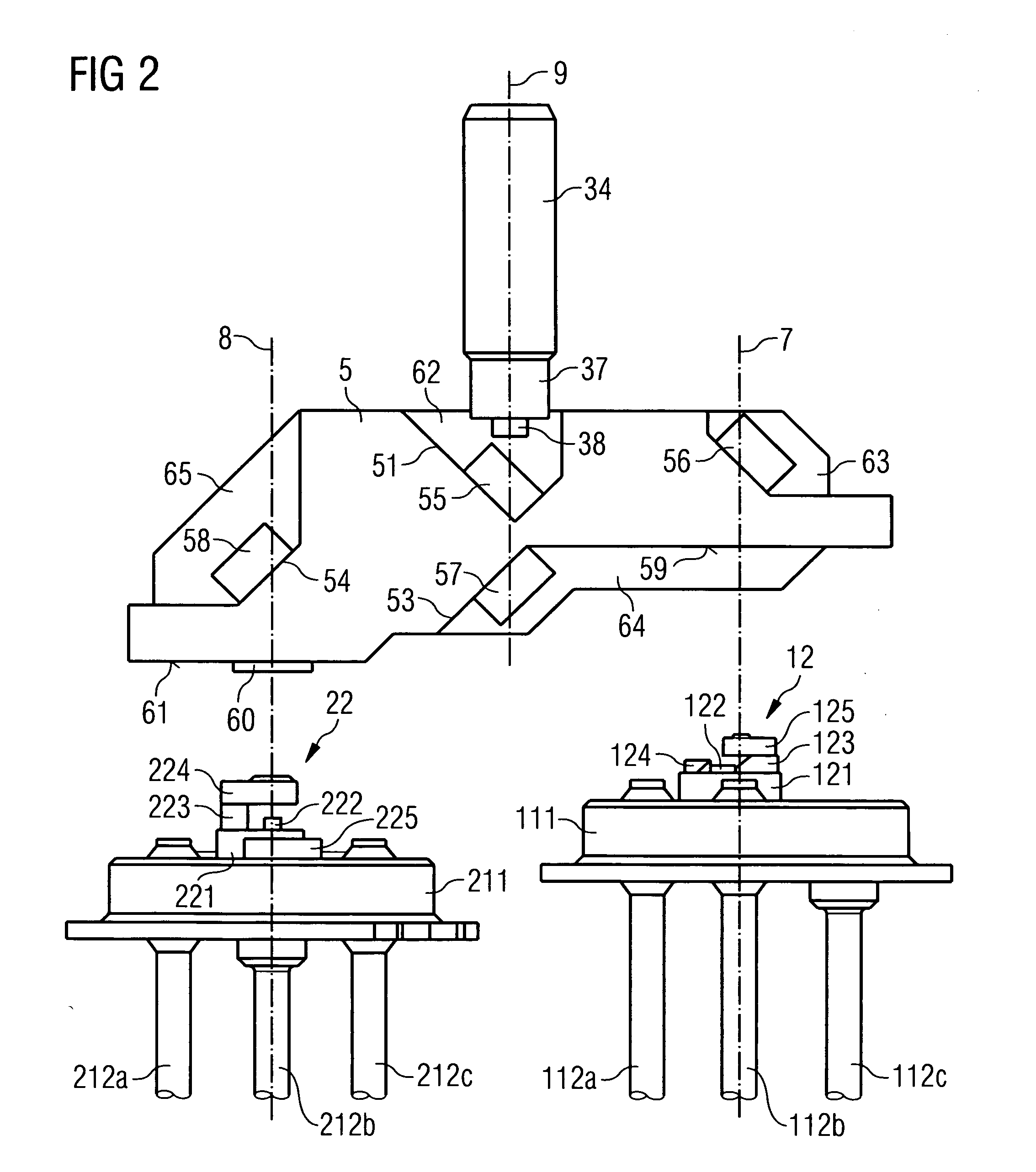
[0042] As can also be seen from FIG. 2 (which is laterally reversed with respect to FIG. 1), the transmitting assembly 12...


PUM


Abstract

An optoelectronic module for optical signals of two optical data channels, the module having a first submodule, which generates or detects optical signals of a first data channel, a second submodule, which generates or detects optical signals of a second data channel, a coupling device for coupling an optical waveguide, a housing, to which the first submodule, the second submodule and the coupling device are mechanically fixed, and a beam splitting device arranged in the housing. The beam splitting device effects beam splitting and light deflection in such a way that a signal transfer is effected on the one hand between the first submodule and a coupled optical waveguide and on the other hand between the second submodule and the coupled optical waveguide, the light of both data channels being multiply deflected in the beam splitting device.

Description

RELATED APPLICATION [0001] The present application claims priority of U.S. Patent Application Ser. No. 60 / 588,784 filed by Volker Plickert and Lutz Melchior on Jul. 16, 2004.FIELD OF THE INVENTION [0002] The invention relates to an optoelectronic module for optical signals of two optical data channels. In particular, the invention provides a bidirectional module for a transceiver of SFF or SFP design that can also be used in passive optical networks. BACKGROUND OF THE INVENTION [0003] So-called small form factor (SFF) transceivers and small form factor pluggable (SFP) transceivers of small design are known. The transceivers may be of pluggable design (SFP transceivers) or be fixedly arranged in a housing on a printed circuit board (SFF transceivers). The known transceivers have, in addition to an optoelectronic transmitting module and an optoelectronic receiving module an internal printed circuit board that runs parallel to the optical axis of the transceiver and contains electronic...

Claims


Application Information

Patent Timeline
IPC IPC(8): G02B6/26
CPCG02B6/4246G02B6/421
Inventor PLICKERT, VOLKERMELCHIOR, LUTZ
Owner EZCONN
Why Eureka
Try Eureka