Receiver for angle-modulated optical signals

a technology of optical signals and receivers, applied in electromagnetic receivers, electrical equipment, electromagnetic transmission, etc., can solve the problems of both optical fields interfering on a photodiode, and no longer sufficed simple photodiodes to extract information from phase- or frequency-modulated signals

Inactive Publication Date: 2006-01-19
NOKIA SIEMENS NETWORKS GMBH & CO KG
View PDF8 Cites 39 Cited by
  • Summary
  • Abstract
  • Description
  • Claims
  • Application Information

AI Technical Summary

Benefits of technology

[0010] The object of the invention is to specify a simple and sensitive receiver for determining the phase information from the transmitted light of an angle-modulated optical signal, and additionally to convert this phase information into an amplitude-modulated electrical signal.
[0017] Significant advantages of the receiver according to the invention are that the sensitivity is increased by up to a factor of 2 compared to self-homodyne reception while being only slightly more complex to implement than same and much simpler than solutions involving an additional laser.

Problems solved by technology

In this case a simple photodiode is no longer sufficient to extract the information from the phase- or frequency-modulated signals.
Both optical fields interfere on a photodiode.

Method used


Image

  • Receiver for angle-modulated optical signals
  • Receiver for angle-modulated optical signals
  • Receiver for angle-modulated optical signals

Examples


Embodiment Construction

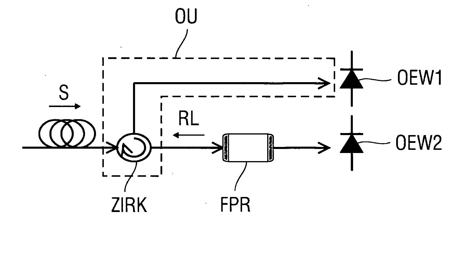
[0023]FIG. 1 shows the value of an improvement factor α of the signal-to-noise ratios between a conventional homodyne receiver and the receiver according to the invention as a function of the signal-to-noise ratios of the input light SNRIn=ES2EN2,

where ES denotes the signal field and EN denotes the noise field of the input signal at the optical resonator.

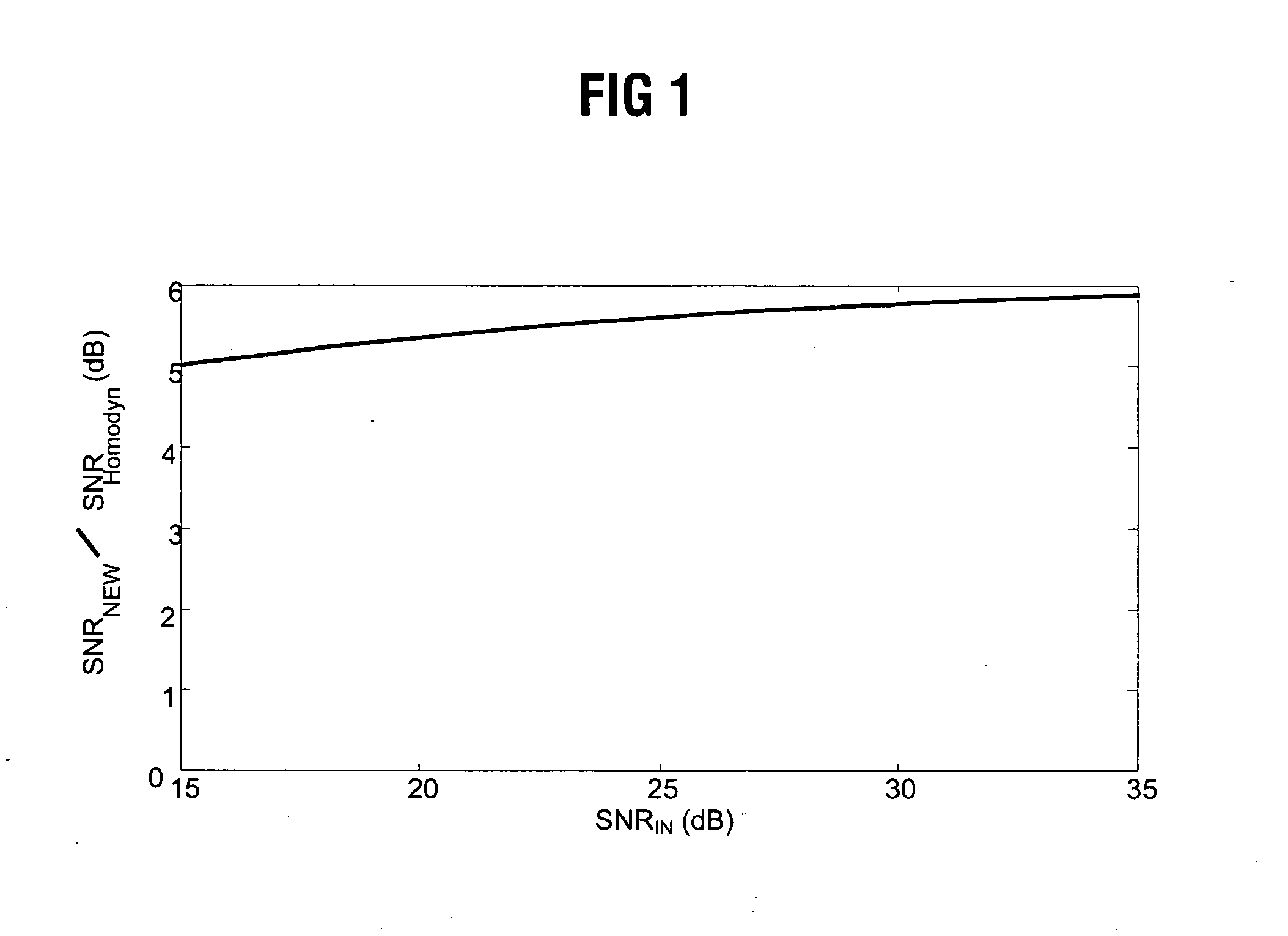
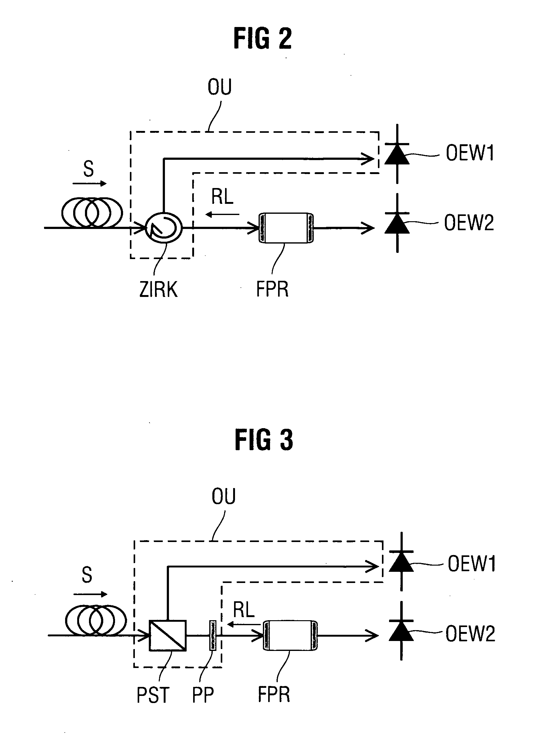
[0024] To clarify the invention in relation to the optical resonator, important resonator parameters will now be explained.

[0025] The characteristics of an optical Fabry-Perot resonator consisting of two mirrors with reflectivity R and spacing L are determined (in simplified form) by the following parameters: [0026] 1. A free spectral range FSR specifies the frequency spacing of the resonator modes. FSR=C2⁢L

where c is the speed of light. [0027] 2. A half-power beamwidth Δv of the resonance is given by Δ𝓋=C2⁢L*1-Rn⁢R.[0028] 3. This yields the following relationship for the finesse F as the quotient of the free spectral range ...


PUM


Abstract

The invention relates to a receiver for an angle-modulated optical signal, whereby the angle-modulated optical signal is injected into an optical resonator. Reflected light escapes from the optical resonator on a phase or frequency change of the angle-modulated optical signal. An optical decoupling device is arranged before the optical resonator, using an opto-electrical converter for determining an angular change in the reflected light from the optical resonator. Various forms of decoupling devices for recovery of the reflected light are described.

Description

CROSS REFERENCE TO RELATED APPLICATIONS [0001] This application is the US National Stage of International Application No. PCT / DE2003 / 003385, filed Oct. 13, 2003 and claims the benefit thereof. The International Application claims the benefits of German application No. 10251889.0 filed Nov. 7, 2002, both applications are incorporated by reference herein in their entirety.FIELD OF THE INVENTION [0002] The invention relates to a receiver for angle-modulated optical signals. BACKGROUND OF THE INVENTION [0003] Existing optical transmission systems modulate the information to be transmitted onto the intensity of the light used for transmission. In a receiving system, a photodiode converts the optical amplitude-modulated signals into electrical signals. In certain configurations or parameter ranges of an optical transmission system, it may be found advantageous to modulate the information onto the phase or frequency of the light to be transmitted. In this case a simple photodiode is no lon...

Claims


Application Information

Patent Timeline
Patent Type & Authority Applications(United States)
IPC IPC(8): H04B10/00H04B10/67H04B10/69
CPCH04B10/69H04B10/675
Inventor ROHDE, HARALD
Owner NOKIA SIEMENS NETWORKS GMBH & CO KG
Why Eureka
Try Eureka