Urine receiver and urine collection processing system implementing urine receiver

a technology of urine receiver and processing system, which is applied in the field of urine tanks, can solve the problems of wearer discomfort, risk of urine leakage, and inability to suction urine within the urine receiver, so as to prevent the overflow the leaking of urine from the urine receiver with more certainty

Inactive Publication Date: 2006-01-19
UNI CHARM CORP
View PDF2 Cites 58 Cited by
  • Summary
  • Abstract
  • Description
  • Claims
  • Application Information

AI Technical Summary

Benefits of technology

[0018] The object of the present invention is to provide a urine receiver which is sanitary, easy to attach, and furthermore, prevents urine leakage even when wearer changes positions repeatedly.
[0041] In addition, a suction part to which a urethral tube is connected is provided between the air-impermeable sheet and the leak-proof part. Through this, if negative pressure is applied to this suction part via a urethral tube in a state wherein the urine discharged from the wearer has reached the air-impermeable sheet, negative pressure is evenly applied within the suction part. As a result, urine is suctioned from the entire surface of the air-impermeable sheet towards the suction part and is suctioned out via the urethral tube. Therefore, because received urine does not remain in one area of the air-impermeable sheet even when the wearer repeatedly changes position, urine leakage from the urine receiver can be prevented.

Problems solved by technology

In the construction described in Patent References 1 and 2, however, urine within the urine receiver cannot be suctioned unless it is led to the vicinity of the end of the urethral tube.
For this reason, if the wearer changes position, the urethral tube is not necessarily located in the section wherein urine is collected, and the risk of urine leaking arises while the wearer repeatedly changes position.
In this case, not only does the wearer feel discomfort, but it is also difficult for the care-giver to attach the supporter onto the wearer.
Therefore, even if attempts are made to suction all of the urine collected in the urine receiver, urine remains within the thick water-resistant sheet and it becomes unsanitary.
Furthermore, because the urine receiver is divided into a urine reception part and a feces reception part, in actuality, the area of the urine reception part which receives urine is small and attaching the urine receiver troublesome.

Method used


Image

  • Urine receiver and urine collection processing system implementing urine receiver
  • Urine receiver and urine collection processing system implementing urine receiver
  • Urine receiver and urine collection processing system implementing urine receiver

Examples


first embodiment

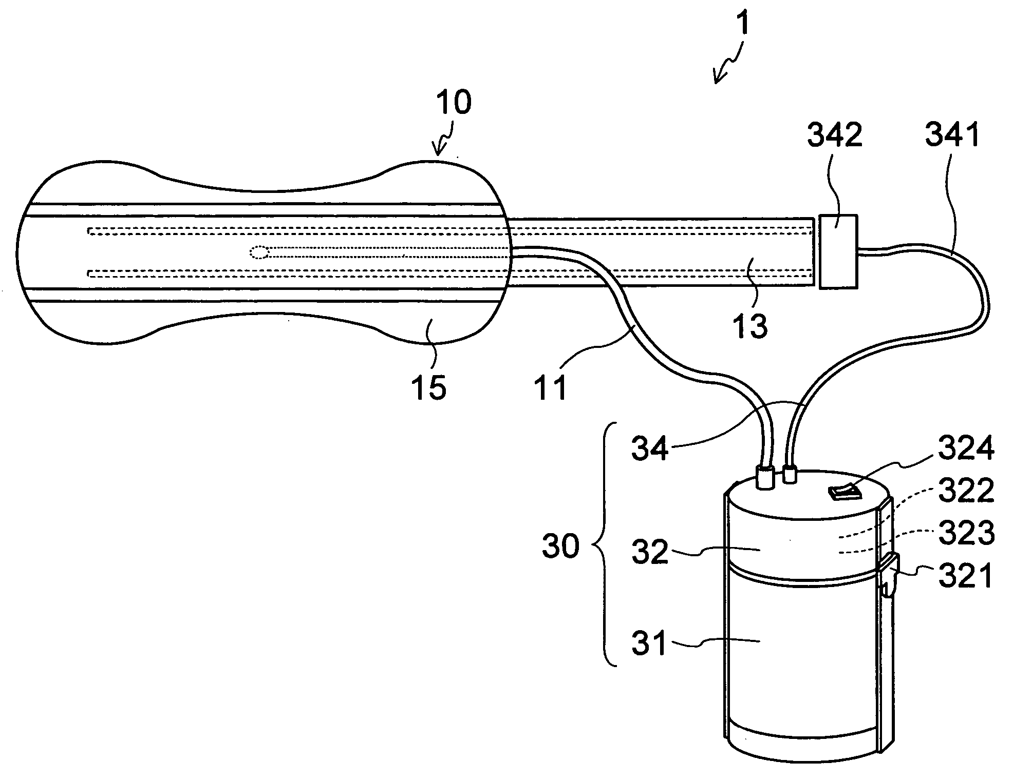
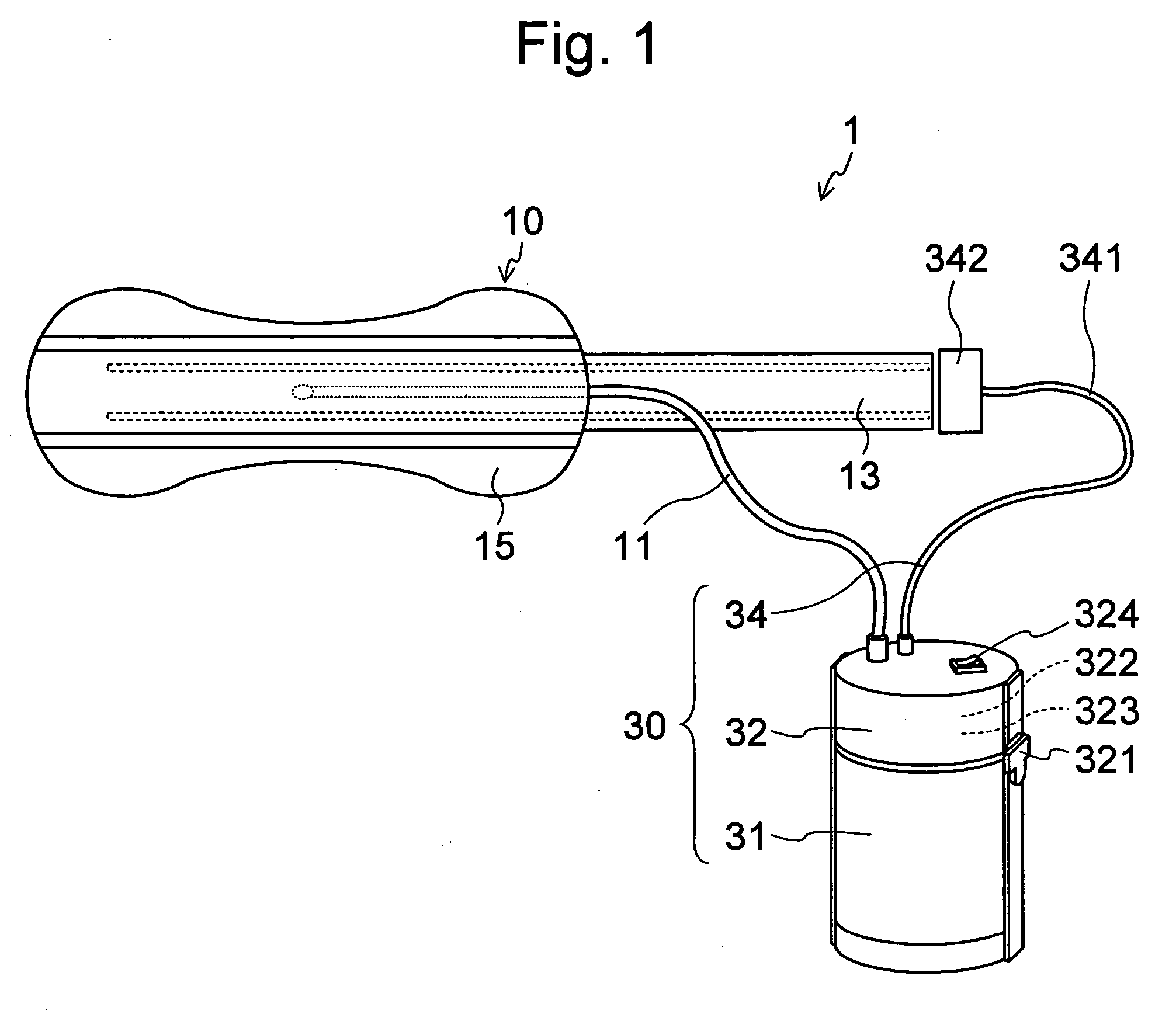
[0063] A perspective pattern view of a urine collection processing device to which a urine receiver according to a first embodiment of the present invention is applied is shown in FIG. 1.

[0064] Urine collection processing device 1 is a device for processing urine discharged by a wearer comprising: a urine receiver 10 for receiving discharged urine; and a main urine collection processing device 30 which is connected to the urine receiver 10 via a urethral tube 11.

[0065] The main urine collection processing device body 30 comprises: a main urine tank body 31 which is connected to the urethral tube 11; a lid part 32 which is provided on the main urine tank body 31 and can be opened and closed; and a urine detection mechanism 34 which extends from the lid part 32 and is connected to the urine receiver 10.

[0066] An un-illustrated water tank which can be removed by opening the lid part 32 is stored within the main urine tank body 31.

[0067] The urine detection mechanism 34 detects urin...

second embodiment

[0136]FIG. 10 is a perspective view of a urine receiver 10A according to a second embodiment of the present invention.

[0137] This embodiment differs from the first embodiment in that the surface sheet in the first embodiment is not provided, the surface material part 14A construction differs, and the main urine receiver body 20A construction differs.

[0138] Specifically, a liquid-passing sheet 24 and a support sheet 25 are layered between the space retention material 23 and leak-proof part 22. The liquid-passing sheet 24 is joined to the support sheet over its entire surface, and the support sheet 25 is joined to the leak-proof part 22 over its entire surface.

[0139] An insertion hole is provided in the leak-proof part 22 and the support sheet for inserting the urethral tube 11.

[0140] In particular, the foregoing urine collection processing device has a construction which differs from the first embodiment in the following ways: [0141] Leak-proof part: PE film with a thickness of 1...

third embodiment

[0146] The present embodiment differs from the second embodiment in that a surface sheet is provided and the surface material part differs.

[0147] More specifically, in order to enhance temporary collection of liquid, the surface material part comprises two layered cushion sheets.

[0148] In particular, the foregoing urine collection processing device has a construction which differs from the second embodiment in the following ways: [0149] Surface sheet: thermal bond nonwoven fabric (25 g / m2 and density of 0.01 g / cm3) [0150] Cushion sheet: thermal bond nonwoven fabric (25 g / m2)


PUM


Abstract

A urine receiver which is sanitary, easy to attach, and furthermore, prevents urine leakage even when a wearer repeatedly changes positions is provided. A urine receiver 10 is implemented in a urine collection processing system wherein urine discharged from the wearer is suctioned into a urine tank via a urethral tube. The urine receiver 10 comprises, at the least: a liquid permeable, air-impermeable sheet 21 which is placed opposite of and covering the urethral meatus of the wearer; a leak-proof sheet 22 which is placed on the surface of the air-impermeable sheet 21 opposite to the urethral meatus and bonds to the outer border of the air-impermeable sheet 21; a suction part 26 which is provided between the air-impermeable sheet 21 and the leak-proof sheet 22 and to which the urethral tube 11 is connected; and a gathers part 16 for sealing the space between the air-impermeable sheet 21 and the wearer's skin surface which is provided on the outer border part of the air-impermeable sheet 21 on the urethral meatus side.

Description

CROSS-REFERENCE TO RELATED APPLICATION [0001] This application is based upon and claims the benefits of priority from Japanese Patent Application No. 2004-209268 filed on Jul. 15, 2004, the entire contents of which are incorporated herein by reference. FIELD OF THE INVENTION [0002] The present invention is related to a urine tank for collecting urine discharged from a wearer and a urine collection processing device comprising this urine tank, which can, for example, assist people such as the elderly, hospitalized patients, and the physically disabled in urination. RELATED ART [0003] Conventionally, there are instances wherein it is difficult for hospitalized patients, physically disabled persons and others to control urination at will. In these instances, urine collection processing devices are used as devices to assist in urination. [0004] The urine collection processing devices, for example, comprise a urine receiver for receiving urine which has been discharged, a urine tank whic...

Claims


Application Information

Patent Timeline
Patent Type & Authority Applications(United States)
IPC IPC(8): A61F5/44A61F5/455
CPCA61F5/451A61F5/44
Inventor SUZUKI, MIOUWADA, ICHIROMIYAGAWA, RYOSUKEISHITSUKA, YOSHIKAZUYOSHIOKA, NOBUAKIKOBAYASHI, JUNICHIMACHIDA, SHIGERU
Owner UNI CHARM CORP
Why Eureka
Try Eureka