
Data collection and analysis system

a data collection and analysis system technology, applied in the field of data collection and analysis system, can solve the problems of difficult individual configuration, inability to properly operate, and thin layer of current data loggers, etc., and achieve the effect of efficient use and more complex signal processing or adjustmen

Active Publication Date: 2006-01-19
KLA TENCOR TECH CORP
View PDF59 Cites 103 Cited by
  • Summary
  • Abstract
  • Description
  • Claims
  • Application Information

AI Technical Summary

Benefits of technology

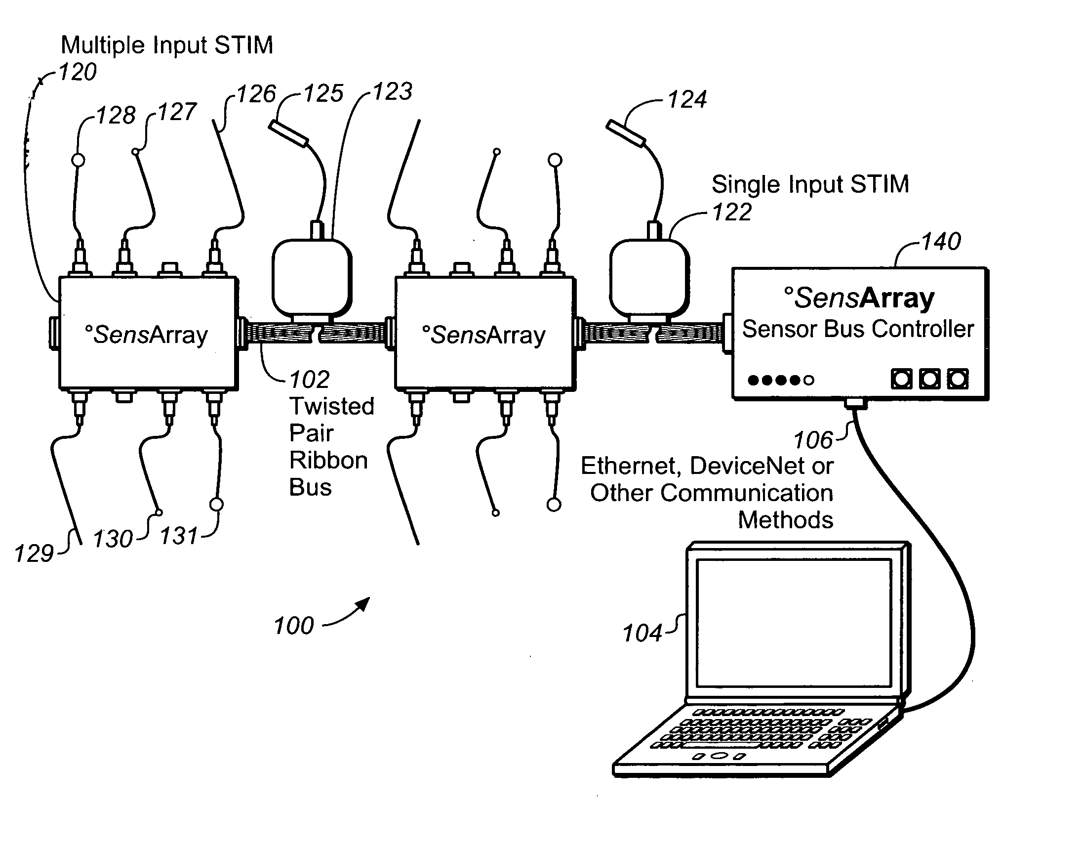
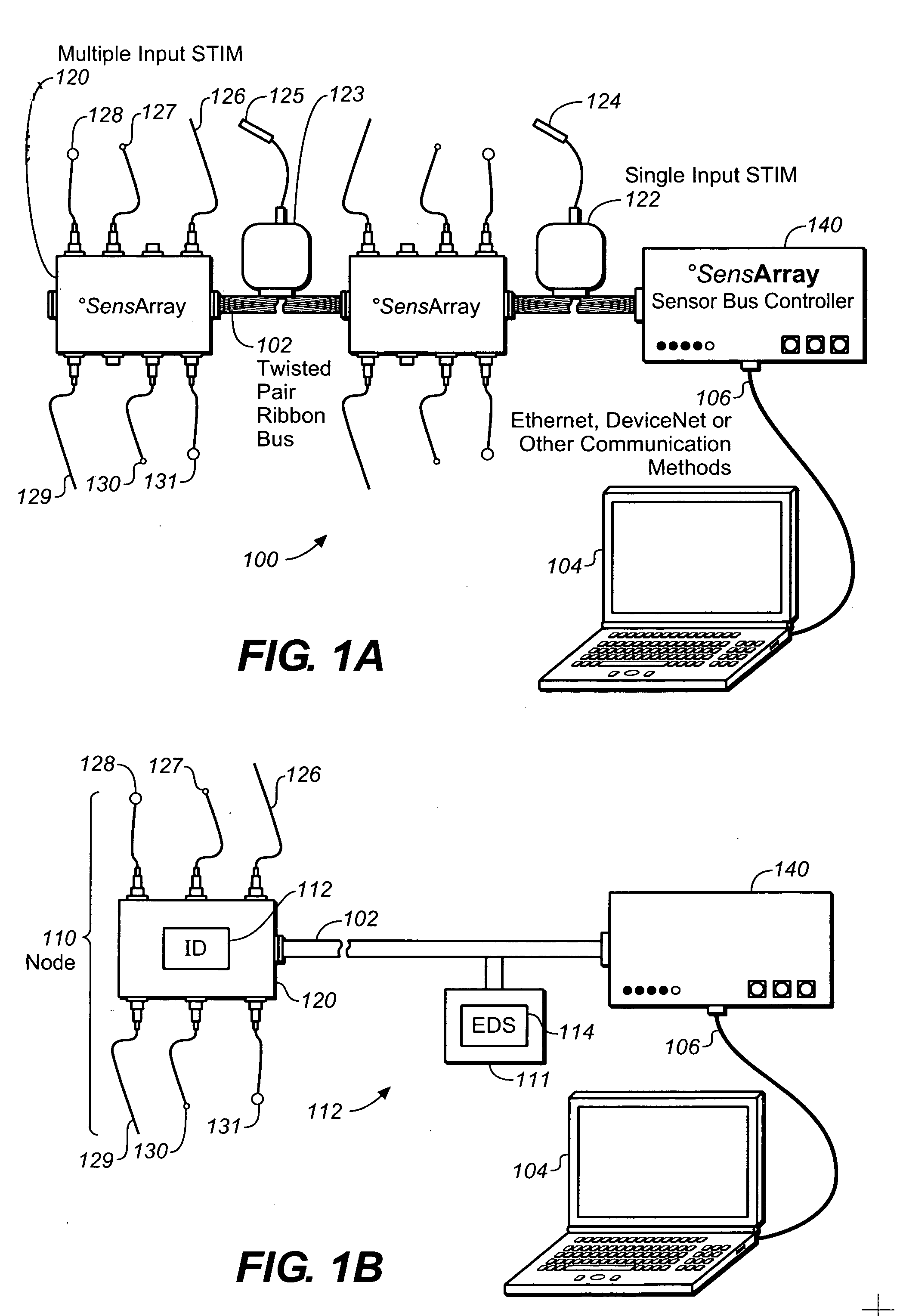
[0008] An apparatus for collecting data includes multiple transducers that are connected to a network by smart transducer interface modules (STIMs). A STIM acts as a signal conditioner and interface unit between a transducer such as a sensor and a local interface controller or a network. A STIM may simply convert an analog input from a sensor to a digital output or may perform more complex signal processing or adjustment. An output may be scaled by a STIM or may be modified by some function. An output of a thermocouple of one type may be converted to mimic the output of a thermocouple of a different type. A ribbon or other type of cable may be used to connect sensors that are attached to a substrate processing tool such as those used in the semiconductor industry. Multiple STIMs may be connected to a ribbon or other type of cable to allow multiple sensor outputs to be accessed over a network. STIMs may be configured to allow different sensors to be sampled at different rates. This may allow the network to be more efficiently used, for instance where different process parameters are measured that change at different rates.
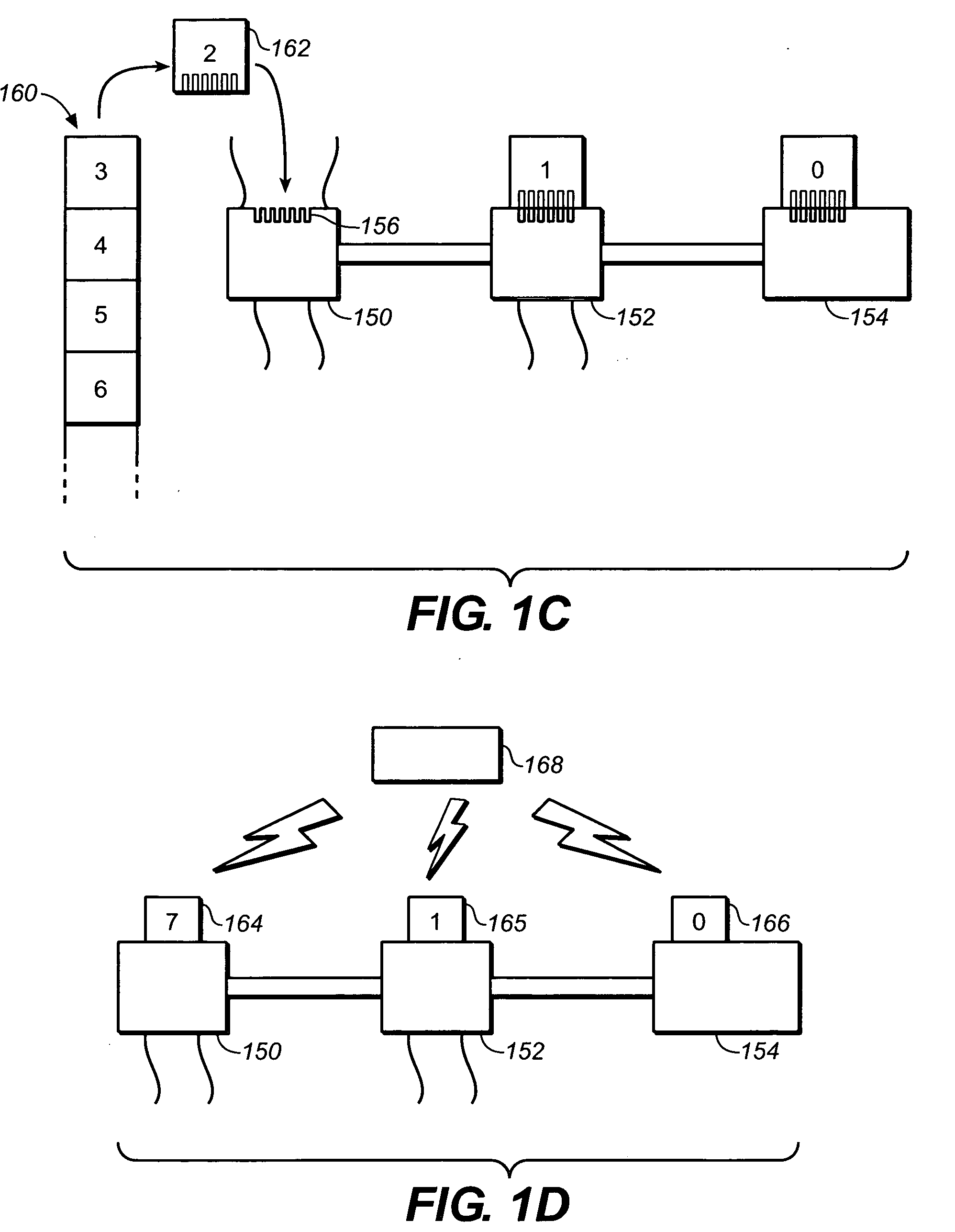
[0009] A sensor network may include one or more memory chips that contain information that helps to configure the data collection, storage and analysis operations of the assembled sensor network or of a platform in communication with the sensor network. Memory chips may be located in a cable, a STIM, a STIM hub, a controller or in a connector. Stored information may include identification data, the types of sensors used and calibration data. By distributing data to dispersed points within a sensor network, configuration and reconfiguration is made easier and may be at least partially automated.

Problems solved by technology

Otherwise, some integrated circuits on a substrate may have too thick or too thin a layer and may not function correctly.
Current data loggers suffer from certain limitations.
Dedicated leads or cables are generally needed for each sensor, sensors may be difficult to individually configure and software used to analyze data is often complex and difficult to customize for a particular application.

Method used


Image

  • Data collection and analysis system
  • Data collection and analysis system
  • Data collection and analysis system

Examples


Embodiment Construction

Data Collection

[0030] Data collection from sensors and other signal producing apparatus on a processing tool may be done in many different ways. Sensors that are part of the tool may be used. In some cases, the tool may be connected so that the outputs of the sensors are sent via a network and are available for analysis. However, such an output may be limited because the configuration of the sensors is determined by the tool manufacturer and may not be easy or acceptable to reconfigure. The locations of the sensors may be fixed so that they are difficult or impossible to move. Also, the frequency with which sensor measurements are sent via the network may be limited to a low frequency such as 1-5 Hertz or lower and may not be configurable by the user. Also, in some systems, data may not be reported regularly in a deterministic or uniform time ordered pattern because of other system operations. Reporting data for data logging may not be a high priority and therefore may not be cons...


PUM


Abstract

A sensor network collects time-series data from a process tool and supplies the data to an analysis system where pattern analysis techniques are used to identify structures and to monitor subsequent data based on analysis instructions or a composite model. Time-series data from multiple process runs are used to form a composite model of a data structure including variation. Comparison with the composite model gives an indication of tool health. A sensor network may have distributed memory for easy configuration.

Description

CROSS REFERENCE TO RELATED APPLICATIONS [0001] This application claims the benefit of U.S. Provisional Application No. 60 / 586,159, filed on Jul. 7, 2004, which application is hereby incorporated by reference in its entirety.BACKGROUND OF THE INVENTION [0002] This invention relates to systems for collecting and analyzing data and using analysis of data for performance monitoring and in particular to the use of such systems on tools that process substrates. [0003] Substrate processing equipment is used to process a variety of different substrates in different industries. Semiconductor substrates, such as silicon wafers, generally go through multiple substrate processing tools during manufacture of integrated circuits. Such tools perform different processes including cleaning, depositing material, removing material, forming patterns on the substrate and heating the substrate. Some tools have different modules that perform different processes such as a cleaning process in a cleaning mod...

Claims


Application Information

Patent Timeline
Patent Type & Authority Applications(United States)
IPC IPC(8): G21C17/00
CPCG05B23/0254
Inventor YETTER, FORREST GILBERT JR.PARKER, JEFFREY M.RENKEN, WAYNE G.PIEPER, JOHN B.
Owner KLA TENCOR TECH CORP
Learn More