Pressure sensor

a technology of pressure sensor and electrode, which is applied in the direction of instruments, semiconductor devices, measurement devices, etc., can solve the problems of easy corrosion of aluminum pads and wirings, and the wirings or pads may be damaged,

Active Publication Date: 2006-01-26
DENSO CORP
View PDF7 Cites 8 Cited by
  • Summary
  • Abstract
  • Description
  • Claims
  • Application Information

AI Technical Summary

Benefits of technology

[0007] In view of the above-described problems, it is an object of the present invention to provide a pressure sensor, which prevents a corrosion of a sensor chip with a simple structure.
[0008] It is another object of the present invention to provide a pressure sensor, which has a corrosion prevention structure while having a small size or / and a reduced component number.
[0010] In the pressure sensor, a second protective film made of an organic material covers at least the surface of the second metal film exposed from the first protective film, and a vicinity of the opening portion of the first protective film. Therefore, the second protective film can prevent a medium (e.g., corrosion medium) from contacting the Al film through the surface of the second metal film and the vicinity of the opening portion of the first protective film. That is, in the present invention, the second protective film directly contacts at least the surface of the second metal film exposed from the first protective film and the vicinity of the opening portion of the first protective film, so as to directly seal this portion. Accordingly, it can prevent the first metal film from being corroded. Furthermore, the structure of the pressure sensor can be made simple, and the number of the components of the pressure sensor can be reduced.
[0011] For example, the second protective film is made of polyimideamide (PEAI) or polyimide (PIQ). Furthermore, the second metal film can be provided approximately on an entire area of the first metal film, and the first protective film can be provided to cover the second metal film. In this case, an exposed area of the first metal film can be further reduced due to the second metal film, and the first metal film is prevented from contacting a corrosion medium.
[0013] The second protective film can be provided to cover an entire surface of the first protective film. In this case, the second protective film can effectively prevent the Al film from contacting a corrosion medium. Furthermore, the first protective film can be formed of an oxidation film, or the second metal film can be constructed of two metal layers of an Au film and a Ti film.

Problems solved by technology

When a pressure sensor is used while a sensor chip is directly exposed in a corrosive liquid, corrosion of wirings or pads may be caused.
For example, in a pressure sensor used for detecting a differential pressure of an exhaust gas filter of a diesel vehicle or for detecting a pressure in an engine room, pads and wirings made of aluminum (Al) may be easily corroded.

Method used


Image

  • Pressure sensor
  • Pressure sensor
  • Pressure sensor

Examples


first embodiment

[0023] The first embodiment of the present invention will be now described with reference to FIGS. 1-5D.

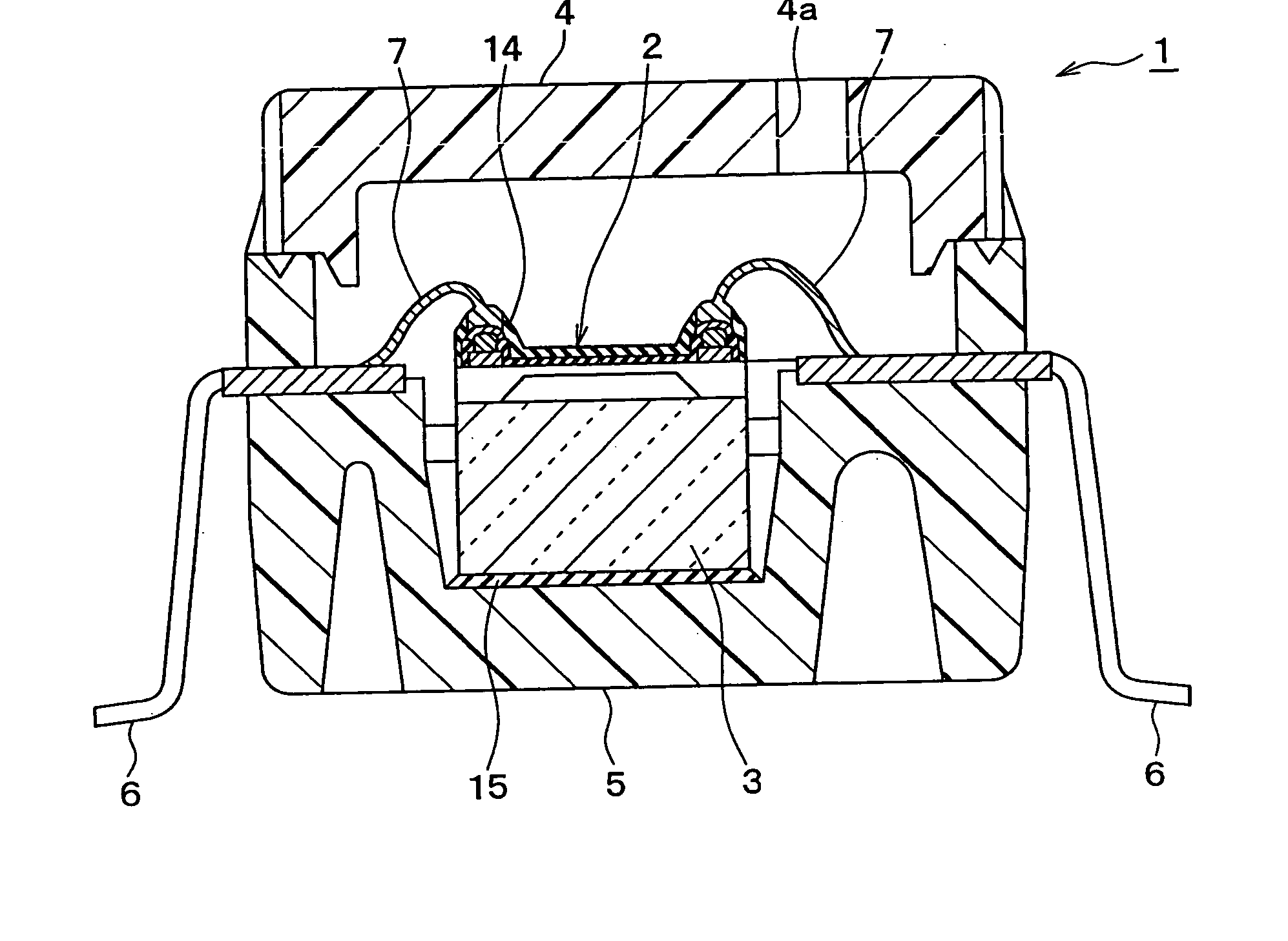
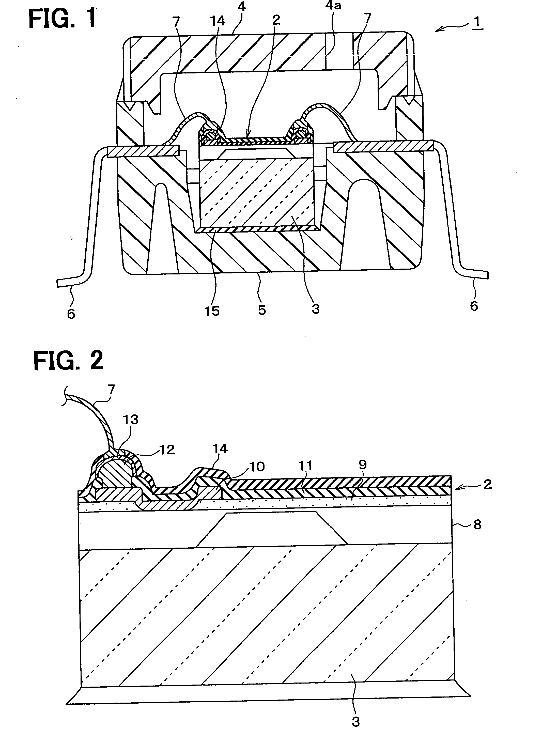
[0024] As shown in FIG. 1, a pressure sensor 1 includes a sensor chip 2, a glass pedestal 3, an upper casing 4, a lower casing 5, terminals 6 and Au wires 7.

[0025] The sensor chip 2 includes a semiconductor substrate 8 in which an electrical circuit including a gauge resistance and a diaphragm are formed, an oxidation film 9 formed on the semiconductor substrate 8, an aluminum film (Al film) 10 electrically connected to the electrical circuit through a conductor hole formed in the oxidation film 9, and a protection film 11 arranged to cover the Al film 10. The protection film 11 has an opening portion from which a predetermined portion of the Al film 10 is exposed. The protection film 11 is composed of two layers of a SiN film and a SiO2 film. The predetermined portion of the Al film 10 is coated by a Ti film 12 and an Au film 13, in this order.

[0026] Because the Au film 13 hav...

second embodiment

[0043] The second embodiment of the present invention will be now described with reference to FIG. 6. In the second embodiment, the structures of the Ti film 12 and the Au film 13 of the first embodiment are changed. FIG. 6 shows a sensor chip 2 of a pressure sensor in the second embodiment.

[0044] As shown in FIG. 6, a Ti film 12 and an Au film 13 are formed approximately on all surface of the Al film 10. Furthermore, the Ti film 12 and the Au film 13 are covered by a protective film 11, together with the Ai film 11. That is, after the Ti film 12 and the Au film 13 are formed on the Al film 10, the protective film 11 covers the surfaces of the oxidation film 9, the Al film 10, the Ti film 12 and the Au film 13, as shown in FIG. 6. The protection film 11 has at least an opening portion through which the Au wire 7 is bonded to the Au film 13. Then, at least the surface of the Au film 13 and the vicinity of the opening portion of the protection film 11 are covered by a protective film...

third embodiment

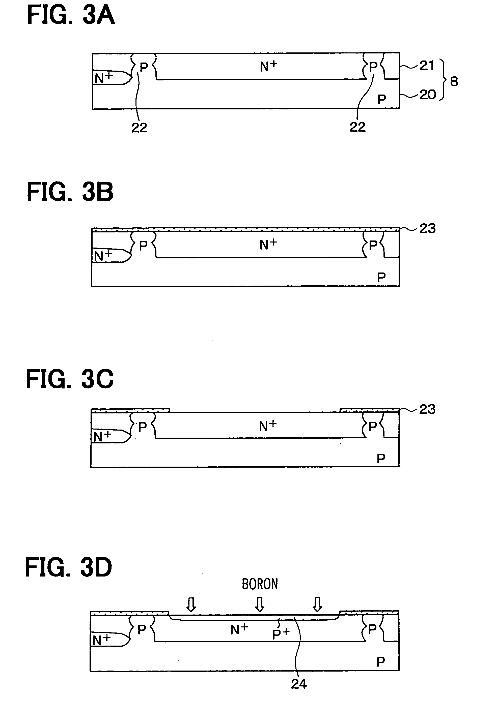
[0048] The third embodiment will be now described with reference to FIG. 7. FIG. 7 shows a sensor chip 2 of a pressure sensor 1 of the third embodiment. In the third embodiment, a Cu film 30 is used instead of the Al film 10 of the second embodiment. When the Cu film 30 is used instead of the Al film 10, an Au plating can be directly performed on the Cu film 30. Therefore, in the third embodiment, the Au film 13 is directly formed on the surface of the Cu film 30, and the Ti film 12 of the second embodiment can be omitted.

[0049] That is, in the third embodiment, after the Au film 13 is formed approximately on all the surface of the Cu film 30, the protection film 11 is formed. Next, the Au wire 7 is connected to the Au film 13, and the protective film 14 covers at least the exposed surface of the Au film 13 and the vicinity of the opening portion of the protective film 11. In this case, the manufacturing method of the pressure sensor 1 can be made simple.

[0050] In the third embodi...


PUM

PropertyMeasurementUnit
gauge resistanceaaaaaaaaaa
corrosion resistanceaaaaaaaaaa
areaaaaaaaaaaa

Abstract

A pressure sensor includes a semiconductor substrate having a diaphragm in which an electrical circuit including a gauge resistance is formed, an insulation film provided on a surface of the semiconductor substrate, an Al film provided on the insulation film and electrically connected to the electrical circuit through a conductor hole of the insulation film, an Au film provided on the Al film through a Ti film, a first protective film which covers the Al film and has an opening portion from which a portion of the Au film is exposed. In the pressure sensor, a second protective film made of polyimideamide or polyimide covers at least the surface of the Au film exposed from the first protective film, and a vicinity of the opening portion of the first protective film. Therefore, corrosion resistance of the Al film can be prevented while the pressure sensor has a reduced component number.

Description

CROSS REFERENCE TO RELATED APPLICATION [0001] This application is based on Japanese Patent Application No. 2004-211630 filed on Jul. 20, 2004, the contents of which are incorporated herein by reference in its entirety. FIELD OF THE INVENTION [0002] The present invention relates to a pressure sensor which can prevent corrosion of wirings in a sensor chip. More particularly, the present invention relates to a pressure sensor in which a sensor chip is directly exposed in a corrosive medium. BACKGROUND OF THE INVENTION [0003] When a pressure sensor is used while a sensor chip is directly exposed in a corrosive liquid, corrosion of wirings or pads may be caused. For example, in a pressure sensor used for detecting a differential pressure of an exhaust gas filter of a diesel vehicle or for detecting a pressure in an engine room, pads and wirings made of aluminum (Al) may be easily corroded. Accordingly, in a pressure sensor described in U.S. Pat. No. 5,595,939 (corresponding to JP patent ...

Claims


Application Information

Patent Timeline
Patent Type & Authority Applications(United States)
IPC IPC(8): G01L9/00
CPCG01L9/0054G01L19/147G01L19/143G01L19/0069H01L2224/45144H01L2224/48091H01L2224/48247H01L2224/48465H01L2224/73265H01L2224/8592H01L2924/16151H01L2924/00014H01L2924/00
Inventor TANAKA, HIROAKITOMISAKA, MANABU
Owner DENSO CORP
Why Eureka
Try Eureka